.png)
Automatic Watering Kit Setup Without Arduino
In this article, we will discuss how the connections should be made for our DIY automatic watering kit. This product will greatly facilitate your watering process for your plants without using Arduino. Let's follow the necessary steps together.
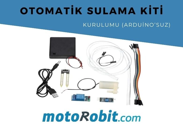
Automatic Plant Watering Kit Material List
The materials required to make our project are;
- Soil Moisture Sensor
- 5v 1 Channel Relay Module
- Mini Water Pump (Submersible Motor)
- Female to Female Jumper Cables
- A power source to power the motor and relay. (You can use a 4-battery holder or any other source capable of providing equivalent energy between 5-9V.)
- Silicone hose suitable for your motor
Our product called DIY Automatic Watering Kit on our website includes all these products. You will only need to purchase external batteries.
Connection Diagram
By carefully checking the connection diagram below, making our connection will be sufficient to operate this project. Let's go through the steps one by one now.
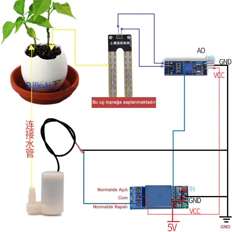
- First, to make the relay module work, we need to supply power to the relay. The relay module has VCC, GND, and IN pins. Connect the positive end of the energy coming from your battery holder or whatever source you are using to the VCC pin. Connect the negative end to the terminal labeled GND. This process will enable your relay to work. Then also provide power from the same source to the terminal labeled Com on your relay. (You can use a different source, but it is more logical to tap the output of a single source to avoid cost.)
- For our motor to work, it needs to receive power from the relay. Connect one end of a cable to the Normally Closed terminal of the relay and the other end to the positive end of our motor. Connect the negative end of the motor to any GND terminal.
- Plug the soil moisture sensor we embedded into the soil into its own circuit board as shown in the photo. The circuit board also needs a 5V power source to work like the relay. Therefore, again provide the positive voltage to the VCC pin and the negative voltage to the GND pin from the same source. This process will make the circuit work. There are two signal outputs on the circuit board. These are the AO (Analog) and DO (Digital) signal outputs. The analog signal output gives us a signal output between 0-5V according to the moisture level of the soil. It increases as it gets drier. The digital one does a binary operation. If the soil is dry, it sends a 5V signal to the relay. If it's wet, it doesn't send. Since we will use this signal, plug the other end of the cable attached to the DO pin into the IN pin of our relay.
- Finally, there is a blue-colored potentiometer on the circuit board of our moisture sensor. This is the part where the sensitivity adjustment is made. With the help of a screwdriver, we can adjust the dryness level at which we want water to come back in trial and error.
Share
Blog Latest Additions
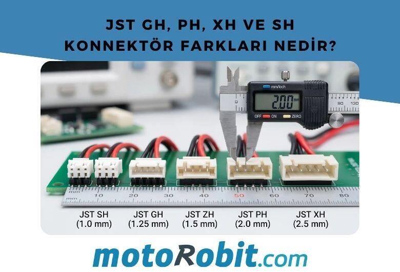
JST GH vs PH vs XH vs SH Connectors: Differences
27.06.2026

Low Level vs. What is High Level Trigger?
19.03.2026

The Code of Numbers on Drone Propellers: How to Read Propeller Measurements?
11.02.2026
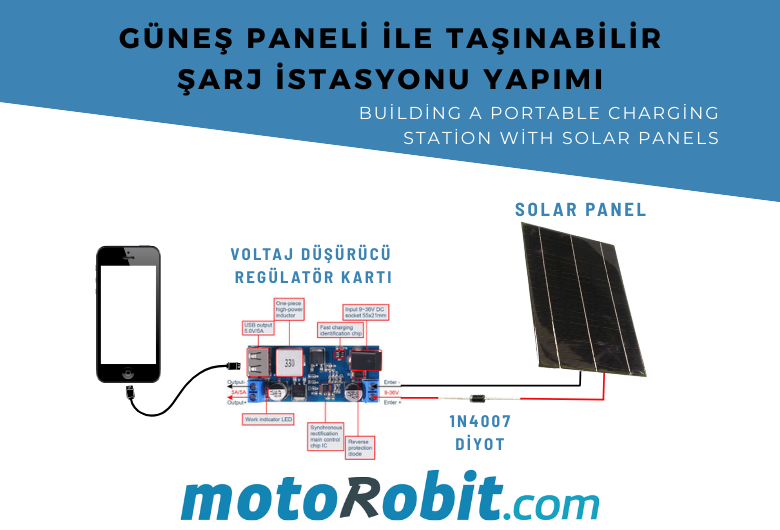
Building a Portable Charging Station with Solar Panels
10.01.2026

Differences Between Li-ion and Li-Po Batteries: Which Battery is Suitable for Which Project?
12.12.2025
MPU-9250: 9-Axis Acceleration Sensor - A Comprehensive Beginner's Guide
28.10.2025