Building a 3D Printer
3D printers, increasingly popular nowadays, have become a curiosity for people from all walks of life. You can make this product at home with varying prices. In this article, we will discuss how to make your own 3D printer and what materials are needed. The printer we will describe how to build was designed by Fatih Bölük. We will list the necessary materials under three headings: materials needed for the chassis, materials needed for movement, and electronic materials.
Materials Needed
Chassis Materials:
- 20x20 Sigma profile 39cm, 2 pieces
- 20x20 Sigma profile 35cm, 2 pieces
- 20x20 Sigma profile 32cm, 3 pieces
- M8mm Induction rod 42cm, 4 pieces (M: Metric)
- M8 Induction rod 37 cm, 2 pieces
- M5 Threaded rod 33cm, 2 pieces
- M6x40 Allen bolt, 6 pieces
- M6 Washer, 6 pieces
- M4x10 Allen bolt, 32 pieces
- M4x40 Allen bolt, 2 pieces
- M4 T-nut, 32 pieces
- M4 Nut, 4 pieces
- M4 Washer, 32 pieces
- M3x40 Flathead screw, 8 pieces
- M3x25 Flathead screw, 5 pieces
- M3x20 Flathead screw, 1 piece
- M3x10 Flathead screw, 3 pieces
- M3x35 Allen bolt, 2 pieces
- M3x25 Allen bolt, 8 pieces
- M3x12 Allen bolt, 6 pieces
- M3x10 Allen bolt, 8 pieces
- M3 Fiber nut, 40 pieces
- M3 Washer, 42 pieces
Motion Components:
- GT2 Pulley, 16 teeth, 2 pieces
- GT2 Belt, 2 meters
- Flexible coupling M5, 2 pieces
- Nema 17 Step Motor, 5 pieces
- Linear bearing sc model M8, 2 pieces or 4 pieces
- Linear bearing lm model M8, 7 pieces
- MK8 Gear, 1 piece
Other Materials:
3D Printer Chassis Assembly
Some parts that need to be removed from the 3D printer will be needed in the chassis assembly, so we recommend printing these parts first. The following steps should be followed one by one.
- Drill holes with an M6 diameter at 10mm inside both ends of the profiles cut to 32cm.
- Use a 6mm guide to tap the ends of the 39cm profile and one end of the 35cm profile. (In the middle of the profile)
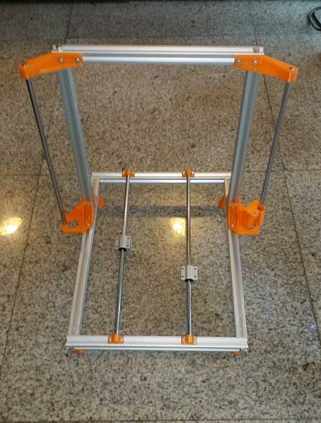
- These parts are assembled to form the base, and the profiles for the z-axis are placed 6cm inside one side of the base. The following visual will give you a better idea about the basic assembly of the chassis.
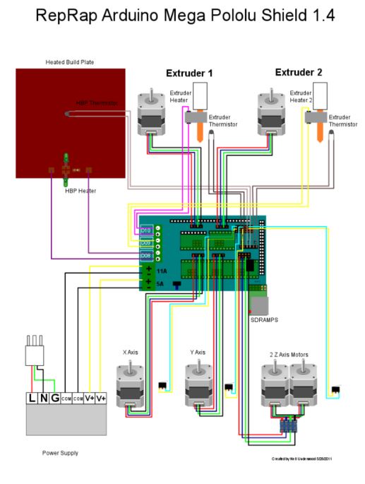
Electrical Connections:
You need to make electrical connections according to the diagram below. We will connect the two step motors controlling the z-axis to a single driver. Therefore, they will be connected to a single driver. Since we only have one extruder, the second extruder connection part will remain empty.
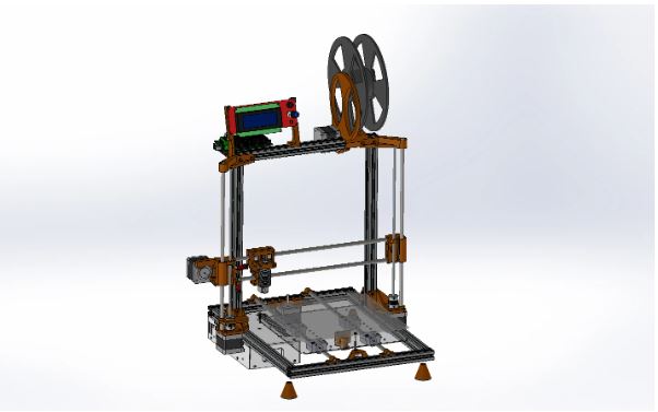
You can access the designs of the tables from this
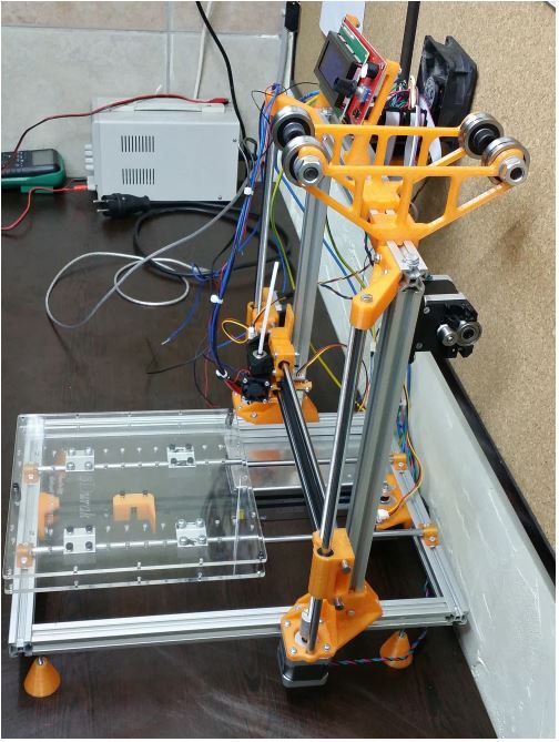
link. Then, you can cut these tables from plexiglass and assemble them. Our final product will be approximately as shown in the image below.
Software Installation:
We will use the open-source code of the Merlin Firmware as our code. You can access the necessary files to download from here. When you transfer the software to the Arduino program, you will see that the software consists of tabs. We will perform our operations in the Configuration.h tab. You can access the necessary settings from this
link.
After making the necessary adjustments, we will upload the software into our Arduino Mega board. We will control our 3D printer through the Repetier program. You can download it from this
link.
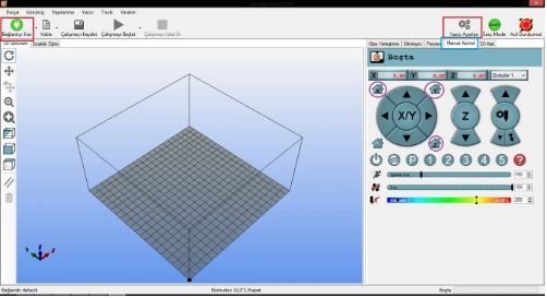
The areas marked with a box and circle in the image are important for us. These areas allow you to establish connections, including setting your baud rate to 250000. The others help you bring your motors to the starting position. Before moving the motors, make sure your hands are on the end switches, and then press to send one axis to the starting position. If the axis goes in the wrong direction, switch false to true or true to false in the code. Then, we will calibrate our printer to move to the specified distance. It's actually just the multiplication of internals and externals. For this, it would be good to have calipers and a fine-point marker. Tell one axis to go to the distance you want, then measure how much it went with calipers and write it down. The formula is: Value to write in the code = Value in the code * Distance I told it to go / Actually gone distance. For example; in my code, it says 78.7402 for the x-axis, I told it to go 50mm, and it went 37mm. The value I will write in my code is 78.7402 * 50/37, which is 104.4056. You will repeat this process for 3 axes and one extruder motor. You will re-upload the code each time. By the way, you cannot establish a connection with Repetier while Arduino is open. If you have done everything well enough and kept your nozzle close enough to the bed, it's time to take your first test print. There is a calibration steps file in the STL files for this purpose, which is ideal. Once your print comes out very well, it means you have a very good printer.
You can access all drawings, connections, and the finished version of the printer's 3D drawing
here.


.png)