.png)
Buzz Wire Game With Arduino
What do you need?
1 x Metal hanger.
2 x 220 ohm resistors.
1 x Breadboard.
1 x Piezo buzzer.
2 x Crocodile Cable.
Various heat shrink tube.
Male-male connecting wires.
1 x Dowel rod.
1 x 7 segment quad display.
1 x 220 ohm resistor.
1 x push button
Male-female connecting wires.
Wooden board.
Assorted wood screws.
Ground
Although this may seem complicated, it's actually a pretty simple project. We will start with the basic structure and then add additional components to increase complexity. You can add whatever you want depending on the ingredients you have.
The main mechanism consists of a shaped wire and a ring on a handle. The player must navigate the loop around the track without two taps. With two taps, the circuit is completed and a buzzer sounds. Of course, it is possible to create this circuit without using a microcontroller, but where's the fun in that?
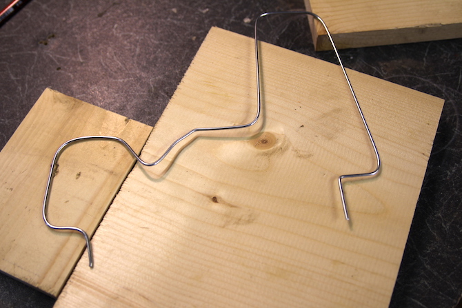
The one on the right is the shape the player must follow in the loop round. It's the foundation of the entire game, so do it well! I decided on a small drop, then prepared for a big climb. Cut a metal hanger into the shape you need. Brass wire or copper tubing works equally well, but a coat hanger may be cheapest.
You may need to wear gloves and use pliers or a hammer to get things perfect. Cut off any excess with bolt cutters. Leave the two ends in an upright position to push them towards the base. Finally, cut two pieces of shrink tubing and place them over the ends
This provides a start/finish or safety zone that isolates the loop from the route. Alternatively, it can be done with tape or even a straw when no heat shrink tubing is available.
Now attach a cable to one end of the track. You have two options here; You can solder it or use a crocodile wire. A alligator cable is the easier option, but soldering may be a more reliable and long-term solution. Make sure to roughen the surface of the coat hanger with sandpaper first.
Depending on the size of the hole you drill in the base in the next step, you may need to feed the cable through the mounting hole first. Using two wires wound together will increase durability:
It's time to lay the groundwork. This serves to keep the track in an upright position and provide a place to attach the electronics. I used some wood, whatever I had around the house, even a cardboard box.
Cut three pieces to create an “n” shape. Screw (or glue) these three pieces together. Remember to drill a hole in the side pieces first to prevent them from coming apart. You may want to countersink the screws, and I recommend a countersink drill bit. A countersinking tool or drill hole Otherwise, a larger diameter drill bit will do.
Drill two holes far enough apart to fit at the ends of the track. Countersink with bottom side ready for gluing.
 Handle
Now it's time to make the handle. Twist a small piece of a hanger at one end to create a loop with a small metal handle. Make sure you bevel the cutting edge and cover it with tape/foam if necessary.
This will form the other half of the circuit - when this ring touches the track it will complete the circuit (like a switch). Solder (or use a crocodile wire) a wire under this as you did of course before.
Cut a small dowel for the actual handle. This metal ring goes into this handle.
Drill a hole through this handle. This needs to be wide enough to fit through the metal ring and cable:
Although this can be difficult, it is possible to do it on a drill. A lathe does the job perfectly:
You can also use a ballpoint pen with the nib removed.
Finally, use hot glue to secure the cable and loop to the handle. Hot glue is a strong fixer, so it will do the trick.
Last part
 Insert the metal wire into the holes in the base. Don't forget to add the cable. Fill the countersink holes on the bottom as shown on the side and use hot glue again to secure it to the base.
Circuit
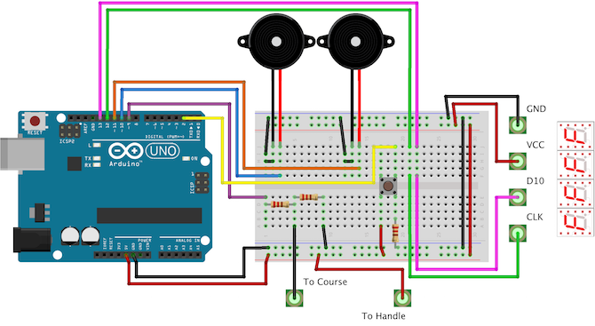
Here is the full circuit. You don't have to make yours this complicated.
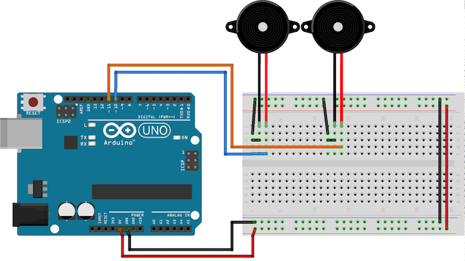
First, connect the two piezo elements to digital pins 10 and 11. Poles don't matter.
You don't have to use two piezos - the only reason I do this is to hear a much louder buzzing sound when the wires make contact. Connect one side to the digital pin and the other to ground.
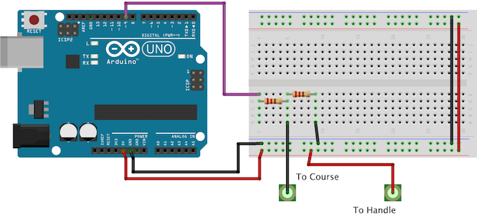
Now install the metal route and handle.
Again, it doesn't matter which direction these two are wired. This part of the circuit is exactly like a button or switch - when the ring touches the track the player completes the circuit. Be sure to add both resistors.
A resistor connects the circuit to ground. The other resistor protects the Arduino. When the two parts are touched, +5V enters the digital pin. If this resistor is missing, there will be a short circuit.
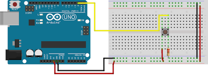
Connect the signal wire (purple in the diagram) to digital pin 9.
Next, connect a button to digital pin 2.
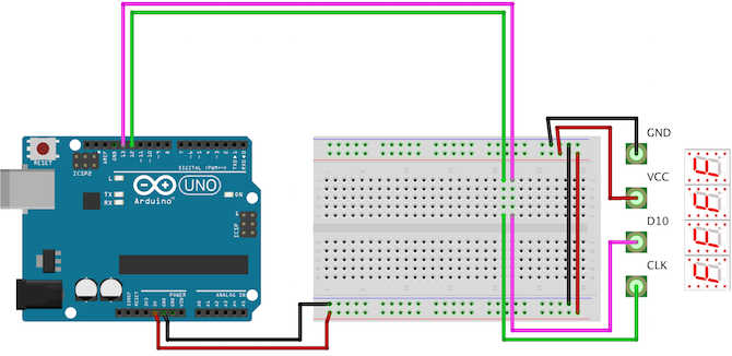
Finally, connect the 7-segment LED display.
This particular model is from Seeed. This uses a TM1637 to manage four displays - meaning only two digital pins are required. Connect GND to Arduino ground and VCC to Arduino +5V. Connect D10 to Arduino digital pin 13 and CLK to digital pin 12.
You can see the diagrams below, according to our narrative order.
Code
You will need two additional files to make this project work. The first step is pitches.h. This file just matches notes with piezo values. For example, it makes writing a melody much easier because you can say "NOTE_C3" instead of "31". These codes, which are publicly available, are available on the Arduino website. Follow the instructions to create a new file called Pitches.h (alternatively paste the code inside your existing script).
Next, you need a method to play notes/melody on the piezo. Anthony DiGirolamo's post on Github has the code you need. Copy everything between “void buzz” and “}}” and paste it into your main file. For reference, here it is:
void buzz(int targetPin, long frequency, long length) {/* Buzzer example function by Rob Faludihttp://www.faludi.comhttps://gist.github.com/AnthonyDiGirolamo/1405180*/long delayValue = 1000000/frequency/2; // calculate the delay value between transitions//// 1 second's worth of microseconds, divided by the frequency, then split in half since//// there are two phases to each cyclelong numCycles = frequency * length/ 1000; // calculate the number of cycles for proper timing//// multiply frequency, which is really cycles per second, by the number of seconds to//// get the total number of cycles to producefor (long i=0; i < numCycles; i++){ // for the calculated length of time...digitalWrite(targetPin,HIGH); // write the buzzer pin high to push out the diaphragmdelayMicroseconds(delayValue); // wait for the calculated delay valuedigitalWrite(targetPin,LOW); // write the buzzer pin low to pull back the diaphragmdelayMicroseconds(delayValue); // wait again for the calculated delay value}}
The last library you need is to check the 7 segment display - you can skip this step if you're not using one. This library is called TM1637 and was created by Seeed, the same company that created the driver board.
In the Arduino IDE, go to “Manage Libraries” (Sketch > Include Library > Manage Libraries). This will bring up the library manager. Wait for it to update and then search for “TM1637” in the search section at the top right. There will be two libraries - "TM1637" is what we need, not "TM1637Display". Select it and then click "install".
The last task is not completed with this library! The library can only display numbers 0-9 and letters A – F. If this covers everything you want to view, you can skip this step. If not, you will need to change the code. Relax! This isn't as difficult as it seems, and if you can write code using the Arduino IDE, you can do it.
First, open your library folder. This will be in your Arduino folder. Open the folder named TM1637. You will need to edit the file called TM1637.cpp - you can safely ignore the other file with the .h extension. Open this file in your preferred text editor, Notepad, or Arduino IDE.
In the third line of code, you can write the following section:
static int8_t TubeTab[] = {0x3f,0x06,0x5b,0x4f,0x66,0x6d,0x7d,0x07,0x7f,0x6f,0x77,0x7c,0x39,0x5e,0x79,0x71};//0~9,A,b,C,d,E,F
static int8_t TubeTab[] = {/* defaults */0x3f, // 00x06, // 10x5b, // 20x4f, // 30x66, // 40x6d, // 50x7d, // 60x07, // 70x7f, // 80x6f, // 90x77, // A -- 100x7c, // b -- 110x39, // C -- 120x5e, // d -- 130x79, // E -- 140x71, // F -- 15/* additional */0x174, // h -- 160x176, // H -- 170x138, // L -- 180x15, // M -- 190x137, // n -- 200x73, // P -- 210x67, // q -- 220x131, // r -- 230x78, // t -- 240x240 // - 25};
Now you can save and close this file. The comment after each item explains which character it is. The next part of the comment is the index of the element.
It's time for the real code. First, add the two previously mentioned libraries:
#include <TM1637.h>#include <pitches.h>
TM1637 *_display = new TM1637(12, 13);
Don't worry if you don't understand - this line tells Arduino that pins 12 and 13 have been added to a 7-segment display and configured accordingly.
The song is stored in "melody" and "tempo". These contain all the notes related to music. If you want to change the music, change these strings. The "songState" variable stores the position of the last played note. This ensures that melodies are played from beginning to end, rather than changing inconsistently.
int songState = 0;int melody[] = {NOTE_F4,...}int tempo[] = {8,...}
Note that I removed the contents of the arrays, see below for the full code.
This code is non-blocking - this means the Arduino can multitask. Timers are set up as follows.
unsigned long previousMillis1 = 0;
const long interval1 = 1500;
There are a few things going on inside the setup() function. First, the inputs and outputs are set. This should be done so the Arduino knows what is connected to each of its pins.
pinMode(9, INPUT); // setup circuitpinMode(10, OUTPUT); // setup buzzer 1pinMode(11, OUTPUT); // setup buzzer 2pinMode(2, INPUT); // setup button
_display->set(5); // set brightness_display->point(false); // remove colon_display->init(); // start display
The set, point, and init methods are all located in the _display object. Instead of a dot, a pointer ("->") is used to access them. Again, don't worry about the syntax.
The main loop has two game modes: timed and free play. Free play allows the player to play for unlimited periods of time. Challenge mode sets a timer for 20 seconds using the "showCountdown" method. Uses the button to start and stop the timer. Currently, the only way to change game modes is to manually edit the variable called "mode". See if you can add another button to do this and change the code accordingly.
The "Buzz" method plays the notes given to it. This is used with "sing". The "sing" method skips and plays the notes. This method is called regular, but it will only play the next note when enough time has passed since the last play. When the song ends, it resets the song to note 1 (songState = 14). You can set this to zero to start the song at the beginning, but the reason for doing this is to skip the intro. The input plays once after the Arduino is turned on and does not play again.
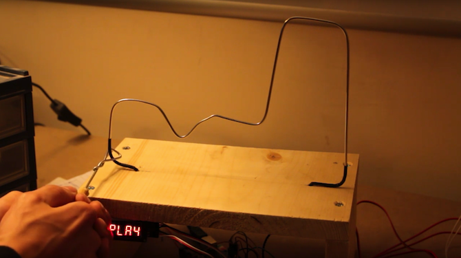
The "ShowFree" and "showPlay" methods write the words "FrEE" and "PLAY" to the screen. Notice that the "r" is lowercase, while all other characters are uppercase. This is one of the limitations of the seven-segment display. They cannot show every letter of the alphabet.
The "ToggleFreePlay" method flashes the screen between "FREE" and "PLAY". Again, it does this in a non-obstructive way.
Another useful method is "showNumber". This writes a number into two characters in the middle of the screen.
The display is not smart enough to know how to display large numbers, it should be clearly stated what to do. This method uses some simple logic to display the appropriate number in each character.
The last method used is called "showCountdown". This starts a counter and decrements it every second. If this reaches zero, it buzzes three times to indicate time has run out.
When all this code is put together, it will look like this:
#include <TM1637.h> // include display library#include <pitches.h> // include pitchesTM1637 *_display = new TM1637(12, 13); // create display object, 12 = CLK (clock), 13 = D10 (data)// musicint songState = 0;int melody[] = {NOTE_F4, NOTE_E4, NOTE_D4, NOTE_CS4,NOTE_C4, NOTE_B3, NOTE_AS3, NOTE_A3,NOTE_G3, NOTE_A3, NOTE_AS3, NOTE_A3,NOTE_G3, NOTE_C4, 0,NOTE_C4, NOTE_A3, NOTE_A3, NOTE_A3,NOTE_GS3, NOTE_A3, NOTE_F4, NOTE_C4,NOTE_C4, NOTE_A3, NOTE_AS3, NOTE_AS3,NOTE_AS3, NOTE_C4, NOTE_D4, 0,NOTE_AS3, NOTE_G3, NOTE_G3, NOTE_G3,NOTE_FS3, NOTE_G3, NOTE_E4, NOTE_D4,NOTE_D4, NOTE_AS3, NOTE_A3, NOTE_A3,NOTE_A3, NOTE_AS3, NOTE_C4, 0,NOTE_C4, NOTE_A3, NOTE_A3, NOTE_A3,NOTE_GS3, NOTE_A3, NOTE_A4, NOTE_F4,NOTE_F4, NOTE_C4, NOTE_B3, NOTE_G4,NOTE_G4, NOTE_G4, NOTE_G4, 0,NOTE_G4, NOTE_E4, NOTE_G4, NOTE_G4,NOTE_FS4, NOTE_G4, NOTE_D4, NOTE_G4,NOTE_G4, NOTE_FS4, NOTE_G4, NOTE_C4,NOTE_B3, NOTE_C4, NOTE_B3, NOTE_C4, 0};int tempo[] = {8, 16, 8, 16,8, 16, 8, 16,16, 16, 16, 8,16, 8, 3,12, 16, 16, 16,8, 16, 8, 16,8, 16, 8, 16,8, 16, 4, 12,12, 16, 16, 16,8, 16, 8, 16,8, 16, 8, 16,8, 16, 4, 12,12, 16, 16, 16,8, 16, 8, 16,8, 16, 8, 16,8, 16, 4, 16,12, 17, 17, 17,8, 12, 17, 17,17, 8, 16, 8,16, 8, 16, 8, 1};// non blocking setup// free playunsigned long previousMillis1 = 0; // time words last changedconst long interval1 = 1500; // interval between changing// musicunsigned long previousMillis2 = 0; // time last changedconst long interval2 = 100; // interval between notesint displayStatus = 0; // keep track of what's displayedint mode = 0; // keep track of game mode -- change to 0 or 1 for different modesbool countdown = false;unsigned long previousMillis3 = 0; // time last changedconst long interval3 = 1000; // interval between countdownint count = 20; // challenge mode timervoid setup() {// put your setup code here, to run once:pinMode(9, INPUT); // setup circuitpinMode(10, OUTPUT); // setup buzzer 1pinMode(11, OUTPUT); // setup buzzer 2pinMode(2, INPUT); // setup button_display->set(5); // set brightness_display->point(false); // remove colon_display->init(); // start display}void loop() {// put your main code here, to run repeatedly:if(mode == 0) {// challenge modeif(digitalRead(2) == HIGH) {delay(25);if(digitalRead(2) == HIGH) {countdown = true; // stop the countdown}else {countdown = false; // stop the countdown}}if(countdown) {showCountdown(); // advance countdown}}else {// free playtoggleFreePlay();}if(digitalRead(10) == HIGH) {delay(25);if(digitalRead(10) == HIGH) {while(digitalRead(10) == HIGH) {buzz(11, NOTE_B0, 1000/24);}}}elsesing();}void showCountdown() {// countdown the time remainingunsigned long currentMillis = millis(); // current timeif (currentMillis - previousMillis3 >= interval3) {previousMillis3 = currentMillis;--count;showNumber(count);if(count == 0) {// game overcountdown = false;count = 20;// reset countdown// buzz 3 timesbuzz(11, NOTE_B0, 1000/24);delay(100);buzz(11, NOTE_B0, 1000/24);delay(100);buzz(11, NOTE_B0, 1000/24);}}}void showNumber(int number) {// show numbers (maximum 99) on display_display->display(0, 25); // write - to segment 1_display->display(3, 25); // write - to segment 4// write number to middle of displayif(number == 10){_display->display(1,1);_display->display(2,0);}else if(number > 9){_display->display(1,1);int newVal = number - 10;_display->display(2, newVal);}else{_display->display(1,0);_display->display(2,number);}}void toggleFreePlay() {// scroll between words without blockingunsigned long currentMillis = millis(); // current timeif (currentMillis - previousMillis1 >= interval1) {previousMillis1 = currentMillis;if(displayStatus == 1)showPlay();elseshowFree();}}void showPlay() {// write "PLAY" to the display_display->display(0, 21); // write P to segment 1_display->display(1, 18); // write L to segment 2_display->display(2, 10); // write A to segment 3_display->display(3, 4); // write Y to segment 4displayStatus = 2;}void showFree() {// write "Free" to the display_display->display(0, 15); // write F to segment 1_display->display(1, 23); // write r to segment 2_display->display(2, 14); // write E to segment 3_display->display(3, 14); // write E to segment 4displayStatus = 1;}void buzz(int targetPin, long frequency, long length) {/* Buzzer example function by Rob Faludihttp://www.faludi.comhttps://gist.github.com/AnthonyDiGirolamo/1405180*/long delayValue = 1000000/frequency/2; // calculate the delay value between transitions//// 1 second's worth of microseconds, divided by the frequency, then split in half since//// there are two phases to each cyclelong numCycles = frequency * length/ 1000; // calculate the number of cycles for proper timing//// multiply frequency, which is really cycles per second, by the number of seconds to//// get the total number of cycles to producefor (long i=0; i < numCycles; i++){ // for the calculated length of time...digitalWrite(targetPin,HIGH); // write the buzzer pin high to push out the diaphragmdelayMicroseconds(delayValue); // wait for the calculated delay valuedigitalWrite(targetPin,LOW); // write the buzzer pin low to pull back the diaphragmdelayMicroseconds(delayValue); // wait again for the calculated delay value}}void sing() {// play the song in a non blocking wayunsigned long currentMillis = millis();if (currentMillis - previousMillis2 >= interval2) {previousMillis2 = currentMillis;int noteDuration = 1000 / tempo[songState];buzz(10, melody[songState], noteDuration);int pauseBetweenNotes = noteDuration;delay(pauseBetweenNotes);// stop the tone playing:buzz(10, 0, noteDuration);++songState;// start song again if finishedif(songState > 79) {songState = 14; // skip intro}}}
Save this file as “buzzwire” (File > Save As) and then upload it to your clipboard (File > Load). Everything is fine, now you should have your own buzz wire game - great!
If you share this project with us when you make it, we would be happy to share it on our social media pages.
Source: https://www.makeuseof.com/tag/make-buzz-wire-game-arduino/

Low Level vs. What is High Level Trigger?

The Code of Numbers on Drone Propellers: How to Read Propeller Measurements?

Building a Portable Charging Station with Solar Panels

Differences Between Li-ion and Li-Po Batteries: Which Battery is Suitable for Which Project?
MPU-9250: 9-Axis Acceleration Sensor - A Comprehensive Beginner's Guide