How does a DC Motor Work?
A DC motor is a machine that converts electrical energy into rotational mechanical energy. Its motion is generated by the physical behavior of electromagnetism. Within DC motors are inductors used to produce motion by generating a magnetic field. But how does this magnetic field change when using DC current?
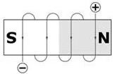
An electromagnet, consisting of a wire coil wrapped around an iron piece with voltage applied to its terminals. If two permanent magnets are added to each side of this electromagnet, attractive and repulsive forces will produce torque.
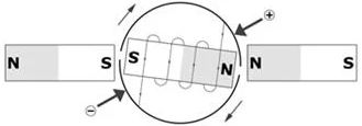
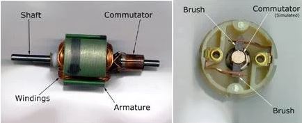
There are two problems to be solved: feeding current to the rotating electromagnet without bending wires, and changing the direction of current at the right time. Both of these problems are solved using two devices: a split-ring commutator and a pair of brushes.
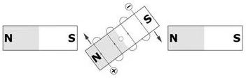
As seen, the commutator has two segments connected to each terminal of the electromagnet, along with two brushes rotating the electromagnet with electric current. Actual DC motors have three segments and two brush slots instead of two.
This way, the polarity of the electromagnet changes as it moves, allowing the shaft to continue rotating. Despite appearing simple and effective, these motors have some issues that make their energy inefficient and mechanically unbalanced, with the main problem arising from the timing between each polar inversion.
44045|44044|43996|43997|43994|37833|43244
How can a DC Motor be Controlled?
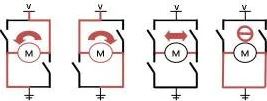
DC motors have only two terminals. Applying voltage to these terminals makes the motor run, reversing the terminal position changes the motor direction. If the motor is running and both terminals are suddenly disconnected, the motor will continue to rotate until it stops. Lastly, if the motor is running and a short circuit is suddenly applied, both terminals of the motor stop.
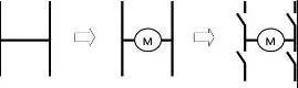
Therefore, there is no third cable to control a DC motor, but its previous behaviors can be designed and solved as a way to control it, and the solution is an H-bridge.
Look at the final evolution of the DC Motor above, you can see there are four gates and there is a motor among them. This is the simplest H-bridge represented by four gates for transistors. By switching these gates and connecting the bottom and top terminals to a voltage source, you can control the motor in all the behaviors below.
Precautions when Using Motors
There is an issue with noise when the motor and line scan camera are connected to the same panel.
The more you turn the PWM on your driving motor, the worse the generated noise will be, and the data retrieved from the camera will look worse than the camera. To significantly reduce this noise, you can directly solder an inductor across two drive motors. This will allow you to increase the vehicle's speed without significantly affecting the data retrieved from the camera.


.png)