.png)
How to make a heart rate monitor with Arduino?
In this blog post, we will explore how to measure pulse with Arduino. To do this, we will use 3 different modules available on our website. These modules are;
Using MAX30100 Heart Rate Sensor with Arduino
The sensor on the device has two LEDs, one emitting red light and the other emitting infrared light. Only infrared light is needed for pulse rate. Both red and infrared light are used to measure oxygen levels in the blood.
When the heart pumps blood, there is an increase in oxygenated blood due to more blood. As the heart relaxes, the volume of oxygenated blood also decreases. The module calculates the pulse rate by knowing the time between the increase and decrease of oxygenated blood.
Oxygenated blood absorbs more infrared light and transmits more red light, while deoxygenated blood absorbs red light and transmits more infrared light. The main function of MAX30100 is to read the absorption levels for both light sources and store them in a buffer that can be read via I2C.
The VIN pin on the sensor is connected to the Arduino's 3V3 pin. GND pins are connected together. The SCL pin is connected to Arduino's A5 pin, and the SDA pin is connected to the A4 pin. The connection diagram of the sensor with Arduino is as shown below.
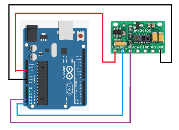
The INT pin on the module is the Interrupt pin and performs the interrupt operation. The IRD pin is the IR LED cathode and LED driver connection point. The RD pin is the red LED cathode and LED driver connection point. Although we do not need to use these pins in the project, it is beneficial to know what they are.
Now, in the Arduino code, we first load the MAX30100.h library and write the following Arduino code to display the heart rate and blood oxygen concentration on the serial monitor. All you have to do is upload the code and bring your finger close to the sensor.
//******************************************************************************
#include "MAX30100.h"
MAX30100* pulseOxymeter;
void setup() {
Wire.begin();
Serial.begin(115200);
Serial.println("Pulse oxymeter test!");
pulseOxymeter = new MAX30100();
pinMode(2, OUTPUT);
}
void loop() {
pulseoxymeter_t result = pulseOxymeter->update();
if( result.pulseDetected == true )
{
Serial.println("BEAT");
Serial.print( "BPM: " );
Serial.print( result.heartBPM );
Serial.print( "SaO2: " );
Serial.print( result.SaO2 );
Serial.println( "%" );
}
}
//****************************************************************************
Using Pulse Heart Rate Monitor with Arduino
The operation of this sensor is almost the same as MAX30100. However, this sensor can only measure heart rate. In MAX30100 sensor, oxygen level in the blood could also be measured.
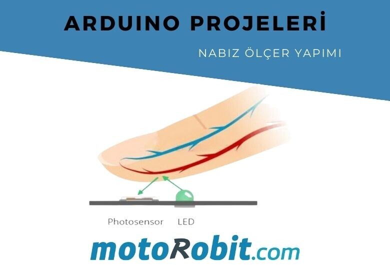
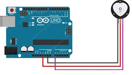
The front side of the sensor is where the heart logo is located. This is where you place your finger. On the front, you will see a small round hole where the green LED, mounted upside down, shines. The working principle of this sensor is based on the green LED here. It works by illuminating the finger with green light (~550nm) and using a photosensor to measure the amount of reflected light.
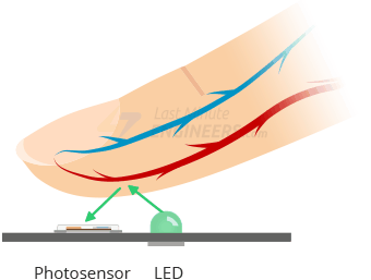
This method of pulse detection through light is called Photoplethysmogram. Oxygenated hemoglobin in arterial blood has the property of absorbing green light. The more red the blood is (the higher the hemoglobin), the more green light is absorbed. As blood is pumped from the finger with each heartbeat, the amount of reflected light changes, creating a changing waveform at the output of the photosensor. As you continue to illuminate and read sensor readings, you will quickly start to receive pulse rate readings.
 The sensor has 3 cables. The black one is GND, the red one is VCC, and the purple one is the analog signal cable. You can see the connections of the sensor in the figure on the side.
For Arduino connections; the VCC pin can be connected to the 3.3V or 5V pin of Arduino. The GND pins are connected together. The analog signal, the purple cable, is connected to the A0 pin. You can see the connection diagram more clearly below.
In the Arduino code, we do not need to load any library for this sensor. We will take the pulse measurement data by taking the average of the last 20 output signals. Here is our Arduino code;
//*******************************************************************************
void setup() {
pinMode(A0, INPUT);
Serial.begin(9600);
}
void loop() {
float pulse;
int sum = 0;
for (int i = 0; i < 20; i++)
sum += analogRead(A0);
pulse = sum / 20.00;
Serial.println(pulse);
delay(100);
}
//********************************************************************************
If you complete these projects, we would be happy to share them on our social media pages.
See you in other projects!
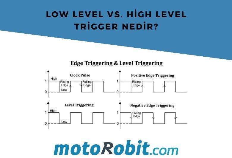
Low Level vs. What is High Level Trigger?

The Code of Numbers on Drone Propellers: How to Read Propeller Measurements?
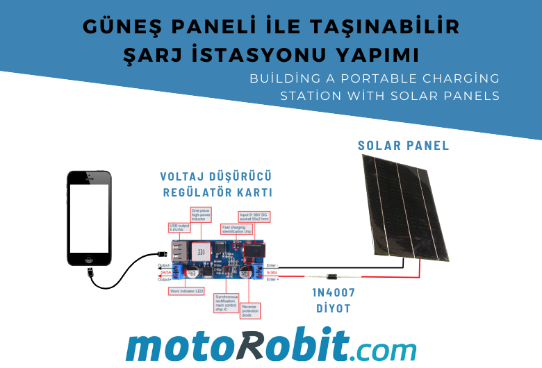
Building a Portable Charging Station with Solar Panels
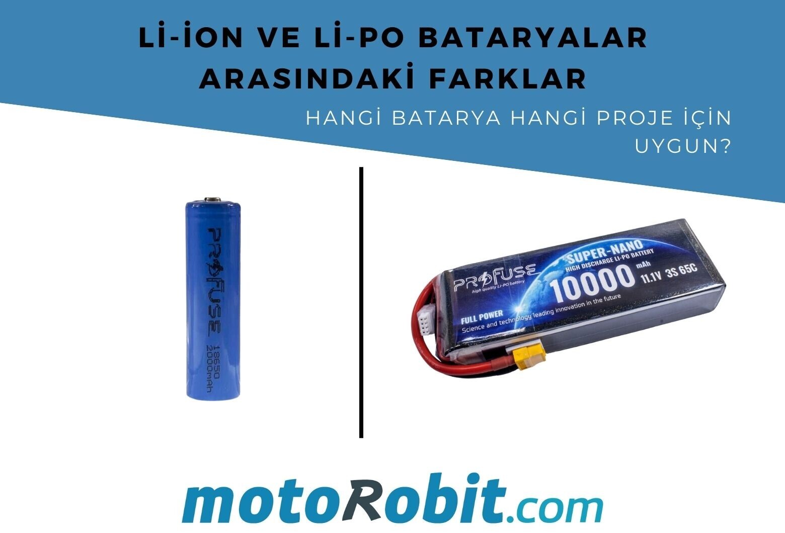
Differences Between Li-ion and Li-Po Batteries: Which Battery is Suitable for Which Project?
MPU-9250: 9-Axis Acceleration Sensor - A Comprehensive Beginner's Guide