.png)
Making a Smoke Detector with MQ-2 Gas Sensor

In this application, we will learn how to detect smoke and combustible gases using the MQ-2 gas sensor. An Arduino project with the MQ-2 gas sensor. With this project that you can easily make at home, you will have a simple smoke detector. If you don't smoke and don't want smoking in your area, this sample project is just for you.
Material List
- Arduino Uno
- Breadboard
- MQ-2 Gas Sensor
- Jumper Cables
- 5mm Red LED
- 5mm Green LED
- Passive Buzzer
- 220 ohm Resistor
The materials listed above will be sufficient to implement this project. As understood from the material list, our project will give warnings with LEDs and sound an alarm through a buzzer when smoke is detected. Our sensor will provide an analog voltage value when it detects smoke, and the Arduino code we will share below is written according to this connection diagram.
MQ-2 Gas Sensor Features
The MQ-2 gas sensor is particularly sensitive to cigarette smoke and the following combustible gases:
- LPG
- Butane
- Propane
- Methane
- Alcohol
- Hydrogen
- The resistance of the sensor varies depending on the type of gas.
The voltage output of the sensor varies depending on the level of smoke/gas in the environment. The sensor provides a voltage output proportional to the concentration of smoke/gas.
In other words, the relationship between voltage and gas concentration is as follows:
- As gas concentration increases, output voltage increases.
- Gas concentration is low, output voltage is low.
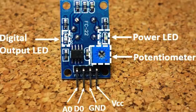
This sensor can provide both analog and digital signal outputs. The A0 output is connected to the Arduino's analog pins and provides a different voltage output according to the smoke level. The D0 pin provides a digital voltage output and is for a presence-absence application. That is, it signals us whether there is smoke or not without measuring density.
MQ-2 Pins
A0 –––––––––––– Analog pins
D0 –––––––––––– Digital pins
GND ––––––––––– GND
VCC ––––––––––– 5V
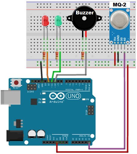
Connection Diagram
We will complete our project using the connection diagram below. It is important to plug the pins into the correct places according to this connection diagram, because our Arduino codes that we will share below are written according to this connection diagram.
Arduino Codes
int redLed = 12;
int greenLed = 11;
int buzzer = 10;
int smokeA0 = A5;
// Your threshold value
int sensorThres = 400;
void setup() {
pinMode(redLed, OUTPUT);
pinMode(greenLed, OUTPUT);
pinMode(buzzer, OUTPUT);
pinMode(smokeA0, INPUT);
Serial.begin(9600);
}
void loop() {
int analogSensor = analogRead(smokeA0);
Serial.print("Pin A0: ");
Serial.println(analogSensor);
// Check if it reaches the threshold value
if (analogSensor > sensorThres)
{
digitalWrite(redLed, HIGH);
digitalWrite(greenLed, LOW);
tone(buzzer, 1000, 200);
}
else
{
digitalWrite(redLed, LOW);
digitalWrite(greenLed, HIGH);
noTone(buzzer);
}
delay(100);
}
Share
Blog Latest Additions

Low Level vs. What is High Level Trigger?
19.03.2026

The Code of Numbers on Drone Propellers: How to Read Propeller Measurements?
11.02.2026

Building a Portable Charging Station with Solar Panels
10.01.2026

Differences Between Li-ion and Li-Po Batteries: Which Battery is Suitable for Which Project?
12.12.2025
MPU-9250: 9-Axis Acceleration Sensor - A Comprehensive Beginner's Guide
28.10.2025
What is ULN2003 ?
13.10.2025