Hello, in this blog post, we will continue with a simple but fun project. We will implement a traffic light application with Arduino. The materials we need for this project are as follows;
1- 1 piece of Arduino
2- 1 piece of Breadboard
3- 3 pieces of 220 Ohm resistors
4- 1 piece of Red LED
5- 1 piece of Yellow LED
6- 1 piece of Green LED
7- And finally, some jumper wires or cables for making connections
Now let's examine how to make connections with these materials from the diagram below.
We will connect resistors to the ends using Arduino's 13, 12, and 11 pins. Then, we will connect the anodes (+) of the LEDs in the order of red, yellow, green to the other end of each resistor. We will collect the cathodes (-) of the LEDs at a single point and connect them to the GND pin of the Arduino. In this way, we will obtain the desired circuit layout.
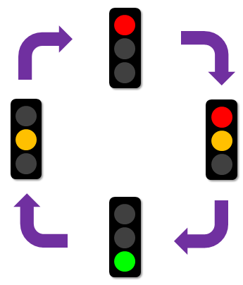 After setting up our circuit, we need to determine our algorithm to write our code. For this, we can think about how traffic lights work. We can better explain our algorithm with the figure next to it and write our code based on this.
As is known, first the red light will turn on. Then the yellow light will turn on with the red light, and then the green light will turn on. After that, the yellow light will turn on alone, and then it will return to the red light. We will do this in a loop manner.
While doing these operations, we also need to consider the durations. For example, the durations of the red and green lights can be equal, but we must determine the duration of the yellow light to be shorter.
According to the loop shown, our code will be as follows. Briefly, without loading any libraries, we only define our pin outputs. Since we have determined our 13, 12, and 11 pins, we define them as outputs with the pinMode function. Then we come to our loop and here, first we turn on the red light and turn off the other LEDs, and we ensure that the red light stays on for 3 seconds. We make the red and yellow lights HIGH simultaneously, and since the yellow light should be short in real life, we leave it on for 1 second. Then we turn on the green light and turn off the other lights, similar to the red light, we do this for 3 seconds. And finally, we turn on the yellow light alone for 1 second. Since the operations are in the Loop loop, the red light will turn on again at the beginning, and this process will continue indefinitely.
//********************************************************************************
void setup()
{
pinMode(13, OUTPUT); // Red LED
pinMode(12, OUTPUT); // Yellow LED
pinMode(11, OUTPUT); // Green LED
}
void loop()
{
// Red
digitalWrite(13, HIGH);
digitalWrite(12, LOW);
digitalWrite(11, LOW);
delay(3000); // 3 seconds wait time
// Red-Yellow
digitalWrite(13, HIGH);
digitalWrite(12, HIGH);
digitalWrite(11, LOW);
delay(1000); // 1 second wait time
// Green
digitalWrite(13, LOW);
digitalWrite(12, LOW);
digitalWrite(11, HIGH);
delay(3000); // 3 seconds wait time
// Yellow
digitalWrite(13, LOW);
digitalWrite(12, HIGH);
digitalWrite(11, LOW);
delay(1000); // 1 second wait time
}
//****************************************************************************
If you do not have the necessary materials, you can try such simple projects online through simulation sites like TinkerCad and make changes to the code to understand better.
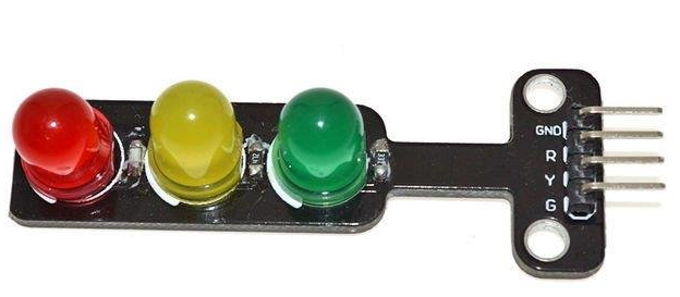
Also, you can perform this project with our "LED Traffic Lights Module - Traffic Light" available on our website!
Whether with LEDs or with the traffic light module we offer for you, if you do this fun project and share it with us, we would be happy to share it on our social media pages.
Thank you for being with us in this short and fun project, see you in the next works!


.png)