.png)
Step Motors: Applications, Types, and Driving with Arduino
Step motors are DC motors that move in different steps. They have multiple coils organized into groups called "phases." By energizing each phase in sequence, the motor will move one step at a time. With computerized step control, you can achieve very precise positioning and/or speed control. Step motors are preferred for highly precise motion control applications. They come in many different sizes, styles, and electrical characteristics. Choosing the right step motor for the job is important.
Applications of Step Motors
Positioning: Step motors are excellent for applications requiring precise positioning, such as 3D printers, CNC machines, camera platforms, and X, Y Plotters, due to their ability to move in precise repeatable steps. Some disk drives also use step motors to position the read/write head.
Speed Control: Precise incremental motion also provides excellent control of speed for process automation and robotics.
Low Speed Torque: Traditional DC motors lack significant torque at low speeds. Step motors have maximum torque at low speeds, making them a good choice for applications requiring high precision at low speeds.
Types of Step Motors
There are many different types of step motors, some of which require highly specialized drivers. Commonly used step motors include Permanent Magnet or Hybrid Step Motors, 2-phase bipolar step motors, and 4-phase unipolar step motors. One of the first things to consider is what the motor needs to do. Larger motors can provide more power. Step motors can range in size from as small as a nut to as large as NEMA 57, for example.
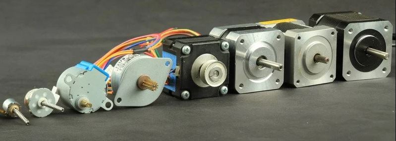
To determine if a motor has the power to do what you want it to do, you need to look at the torque value. NEMA 17 Step Motors, for example, are a common size used in 3D printers and small CNC projects. Smaller motors are used in many robotic and animatronic applications. Larger NEMA-sized motors are common in CNC machines and industrial applications. NEMA numbers define the standard mounting plate size for the motor but do not define other characteristics of the motor. Two different NEMA 17 motors could have completely different electrical or mechanical characteristics.
Step Count
The next point to consider is the resolution of the positioning you desire. The number of steps per revolution ranges from 4 to 400. Commonly used step counts are 24, 48, and 200 steps per revolution. Resolution is often expressed in degrees per step. A 1.8-degree motor is equivalent to a 200 steps/revolution motor.
Unipolar vs Bipolar
Unipolar drivers always energize the phases in the same way. One coil, the "common" coil, will always be negative. The other coil will always be positive. Unipolar drivers can be implemented with a simple transistor circuit. The disadvantage is that there is less available torque since only half of the coils can be energized at a time.
Bipolar drivers use an H-bridge circuit to actually reverse the current flow in the phases. By reversing polarity and energizing the phases, all coils can start attempting to turn the motor.
In a two-phase bipolar motor, there are 2 groups of coils. A 4-phase unipolar motor has 4. In a two-phase bipolar motor, there are 4 wires for each phase. Some motors come with flexible cables that allow you to operate the motor in either bipolar or unipolar mode.
5-Wire Step Motor
Common in small unipolar motors. All of the common coil wires are connected to a 5th wire pulled out. This motor can only be driven as a unipolar motor.
6-Wire Step Motor
Combines the common wires of 2 matched phases. These two wires can be combined to create a 5-wire unipolar motor.
You can ignore and treat it like a bipolar motor!
8-Wire Step Motor
An 8-wire unipolar is the most versatile motor of them all. It can be driven in various ways:
4-phase unipolar - All common wires are connected together - just like a 5-wire motor.
2-phase series bipolar - Phases are connected in series - like a 6-wire motor.
2-phase parallel bipolar - Phases are connected in parallel. This results in half the resistance and inductance - but requires twice the driver current. The advantage of this wiring is higher torque and maximum speed.
Finding Step Motor Pins
The best solution is to obtain the pinout from the motor manufacturer. If you don't have the pinout diagram, the following procedure will help you find it yourself.

4-Wire Step Motor
When you measure with a multimeter, both phases should have the same resistance . When measuring the resistances in the wires using the Ohm scale, the two wires that show resistance are the ends of the same coil. When we call one of these ends A1 and the other A2, the remaining 2 wires are B1 and B2. This way, we find the wires of the motor. If the motor rotates in reverse, reverse either A1 and A2 or B1 and B2.
6-Wire Step Motor
After setting the multimeter to the ohm scale, connect one wire to one end of the multimeter and measure the resistance with the other wires. You will get resistance values from 2 wires. In 6-wire step motors, there is a center wire for each phase. The resistance value between the center wire and the other wires is half the resistance value between A1 and A2. You can find the wires by measuring with a multimeter. You can also do the same measurements on the other 3 wires to find the B1 and B2 ends. If the motor rotates in reverse, reverse either A1 and A2 or B1 and B2.
How to Drive a Step Motor?
Driving a step motor is slightly more complex than driving a DC motor. Step motors require a step controller to energize the phases to make the motor rotate. Let's examine step motor usage with Arduino using A4988 Step Motor Driver and TB6600 Step Motor Driver.
Using A4988 Step Motor Driver with Arduino
A4988 Motor Driver is a microstep driver for controlling bipolar step motors with an integrated converter for easy use. This means that our step motor controller can be controlled with just 2 pins or one to control the direction and the other to control the steps.
The driver offers five different step resolutions: full step, half step, quarter step, eighth step, and sixteenth step. It also has a potentiometer to adjust current output, thermal shutdown for over-temperature protection, and crossover current protection. The logic voltage is between 3 and 5.5 V, and with good cooling, the maximum current per phase is 2A.

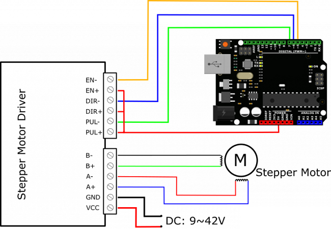
Using TB6600 Step Motor Driver with Arduino
TB6600 Motor Driver is an easy-to-use professional step motor driver that can control two-phase step motors. It is compatible with Arduino and other microcontrollers that can provide a 5V digital signal. The TB6600 Arduino step motor driver has a wide power input of 9 to 42VDC. And it can provide a peak current of 4A, which is sufficient for most step motors.
The driver supports speed and direction control. You can adjust microstepping and output current with 6 DIP switches. It offers 7 microstepping options (1, 2/A, 2/B, 4, 8, 16, 32) and 8 current control options (0.5A, 1A, 1.5A, 2A, 2.5A, 2.8A, 3.0A, 3.5A).
As a professional device, it can drive two-phase, four-phase, and hybrid step motors.
Share
Blog Latest Additions
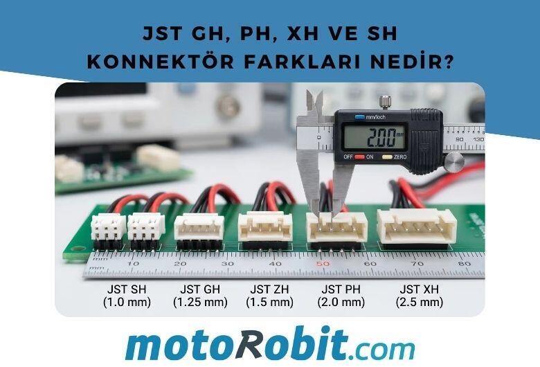
JST GH vs PH vs XH vs SH Connectors: Differences
27.06.2026
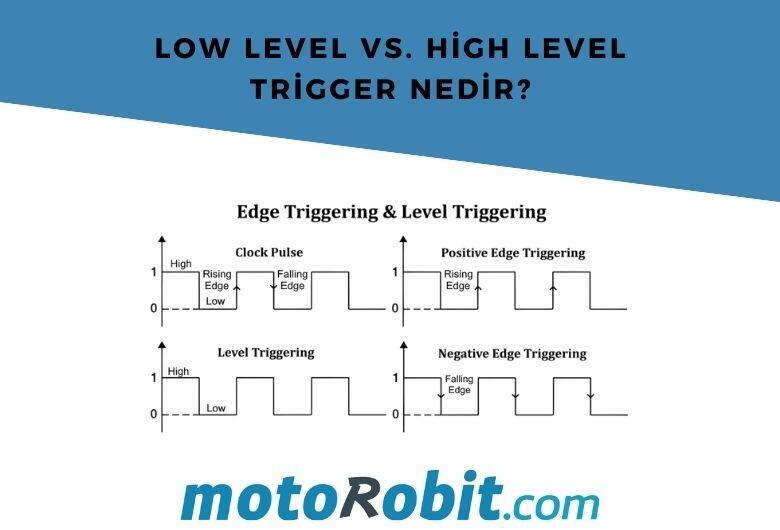
Low Level vs. What is High Level Trigger?
19.03.2026

The Code of Numbers on Drone Propellers: How to Read Propeller Measurements?
11.02.2026
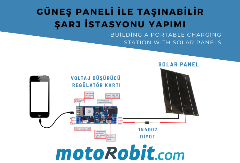
Building a Portable Charging Station with Solar Panels
10.01.2026
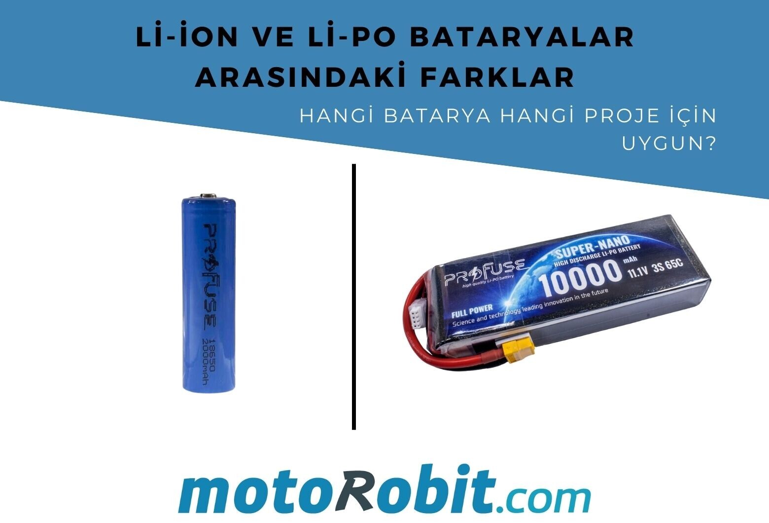
Differences Between Li-ion and Li-Po Batteries: Which Battery is Suitable for Which Project?
12.12.2025
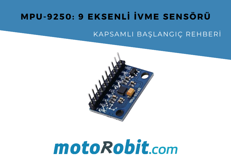
MPU-9250: 9-Axis Acceleration Sensor - A Comprehensive Beginner's Guide
28.10.2025