.png)
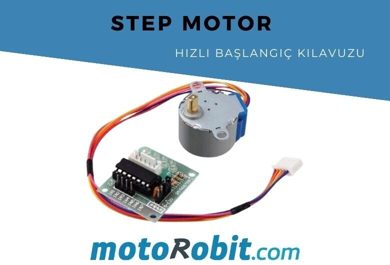
Stepper Motor Quick Start Guide
There are many motors to choose from, and sometimes it's uncertain which one will be best for your application. In this article, we'll discuss how to choose one of these motors, a stepper motor and alternatives, the best way.
How it Works
Stepper motors are distinguished from normal DC motors by their ability to rotate with very precise increments instead of just in one direction. Imagine a motor in an RC plane. The motor rotates very quickly in the direction you want. You can adjust its speed by varying the amount of power supplied to the motor, but you can't tell the propeller to stop at a specific position. Now imagine a printer. There are many moving parts inside the printer, including motors. One of these motors can move the paper while another can move the print head. For this motor to print the next line of text or the next image, it needs to move the paper a precise distance. There's another motor connected to a gear rod that moves the print head back and forth. Again, this gear rod needs to be moved a certain distance to print a letter after letter. This is where stepper motors come in handy.
Stepper motors can move in degrees (or steps). This allows you to have complete control over the motor, move it to a location, and hold that position. It does this by briefly energizing the coils inside the motor. You always need to provide power to keep the motor in the position you want. We won't go into too much detail here, but you can check out our other articles about stepper motors for more information. For now, all you need to know is that to move a stepper motor, you need to specify its direction and speed.
There are many types of stepper motors and driver boards available. In the example below, you can see how to connect a stepper motor to an Arduino and control it.
Controlling a Step Motor with Arduino
We'll examine how to control, mount, and connect your motor using code loaded onto an Arduino with the A3967 Step Motor Driver board.
Assembly
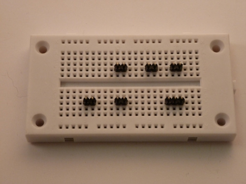
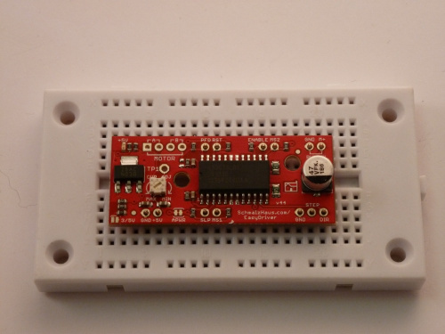
The easiest way to use the driver board is to solder headers onto it for easy placement on a breadboard. Alternatively, you can solder the headers directly to the board.
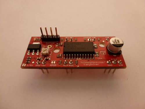
The first step is to solder male headers onto the driver board. In this example, very few of the actual pins on the driver board will be used. However, it's recommended to use all the broken pin headers for added stability when attached to the breadboard. A simple method for this is to cut the desired number of headers, place them in suitable positions on the breadboard, place the driver board on top, and then solder all connections.
Once all headers are soldered, it's time to connect your driver board to your Arduino. Make all the necessary connections using the image below.
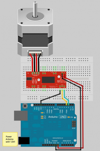
Note: The small stepper motor looks different from the one in the picture. It should have a 4-pin connector at the end. This will be connected to a 4-pin male header with the wires facing up. Due to the nature of this stepper motor, you can connect the connector to the black wire or the yellow wire on the left. Either way will work. If you're using a different motor, you can check out our other article on stepper motors to find out where to connect the wires.
Important: Stepper motors require more power than can be provided by Arduino alone. In this example, we'll give power to the Uno with an external 12V supply. Note that the power input (M+) on the driver board is connected to the Vin pin on the Arduino. This allows you to power both the Arduino and the motor with the same power source.
Software
Once everything is connected correctly, you can upload the software to the Arduino. The code below is a very simple example code, but you can find many examples, including the Stepper library included with the Arduino IDE. Feel free to play with this code, change the values to see what happens, and explore other codes.
------------------------------------------------
int dirpin = 2;int steppin = 3;void setup() {pinMode(dirpin, OUTPUT);pinMode(steppin, OUTPUT);}void loop(){ int i; digitalWrite(dirpin, LOW); // Set the direction. delay(100); for (i = 0; i<4000; i++) // Iterate for 4000 microsteps. { digitalWrite(steppin, LOW); // This LOW to HIGH change is what creates the digitalWrite(steppin, HIGH); // "Rising Edge" so the easydriver knows to when to step. delayMicroseconds(500); // This delay time is close to top speed for this } // particular motor. Any faster the motor stalls. digitalWrite(dirpin, HIGH); // Change direction. delay(100); for (i = 0; i<4000; i++) // Iterate for 4000 microsteps { digitalWrite(steppin, LOW); // This LOW to HIGH change is what creates the digitalWrite(steppin, HIGH); // "Rising Edge" so the easydriver knows to when to step. delayMicroseconds(500); // This delay time is close to top speed for this } // particular motor. Any faster the motor stalls.}------------------------------------------------
Now that you've figured out how to run your stepper motor at the simplest level, it's time to move to the next level. You can learn what you can do with other stepper motor driver boards.
You can get support from our robotikbilgi.com website for the topics you want help with.
Source: https://www.sparkfun.com/tutorials/400
Share
Blog Latest Additions
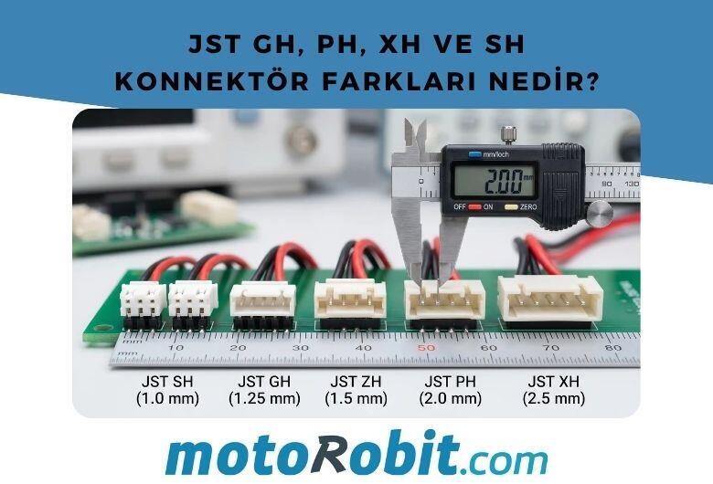
JST GH vs PH vs XH vs SH Connectors: Differences
27.06.2026
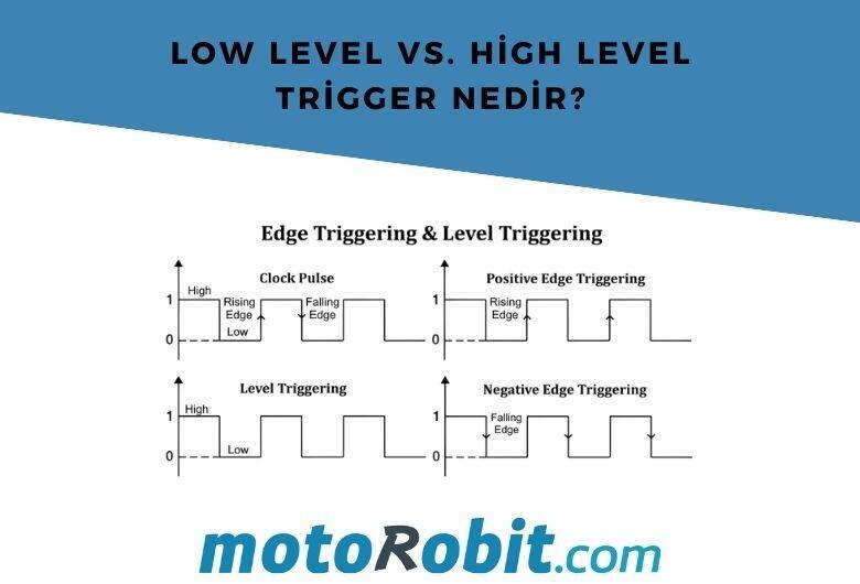
Low Level vs. What is High Level Trigger?
19.03.2026
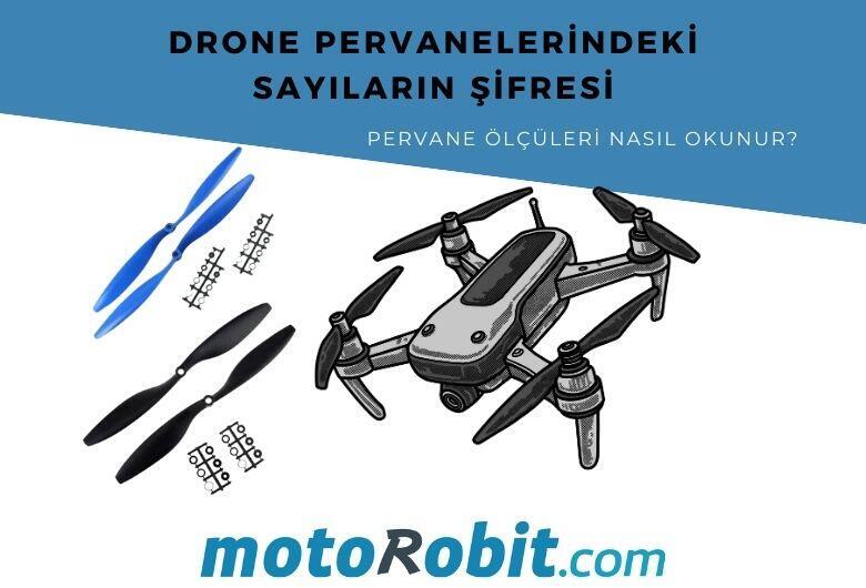
The Code of Numbers on Drone Propellers: How to Read Propeller Measurements?
11.02.2026
Building a Portable Charging Station with Solar Panels
10.01.2026
Differences Between Li-ion and Li-Po Batteries: Which Battery is Suitable for Which Project?
12.12.2025
MPU-9250: 9-Axis Acceleration Sensor - A Comprehensive Beginner's Guide
28.10.2025