.png)
Using Keypad with Arduino / Smart Lock Project
In this blog post, we will examine how to use a keypad with Arduino. First, we will discuss how to connect a keypad to Arduino and how it works. Then, we'll delve into its usage with a 2x16 LCD screen, and finally, we'll talk about creating a smart lock project using a 5V relay.
In this example, we will use a 4x4 matrix membrane keypad, but there are also code and connection diagrams available for 3x4 matrix keypads. Membrane-style keypads are ideal for most projects because they are thin and can be adapted to many places thanks to the adhesive surface on the back.
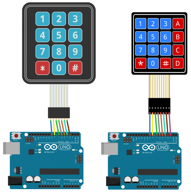
Keypad Arduino Connection Diagram
For most membrane keypads, the pin layout is as follows:
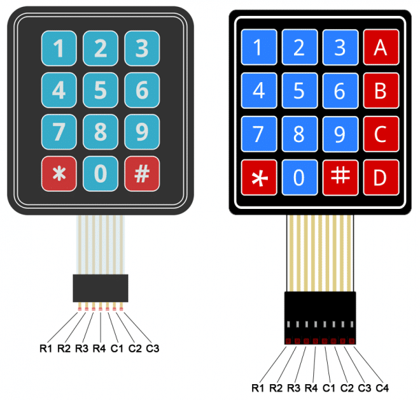
To connect 3x4 or 4x4 keypads to your Arduino, you can use the following connections:
Keypad Library
We will use Mark Stanley and Alexander Brevig's Keypad library. This library pays attention to setting pins and scanning different rows and columns. You can download the library here.
Arduino Keypad Codes
After loading the Keypad library, if you are using a 4x4 keypad, you can upload this code to Arduino:
#include <Keypad.h>
const byte ROWS = 4;
const byte COLS = 4;
char hexaKeys[ROWS][COLS] = {
{'1', '2', '3', 'A'},
{'4', '5', '6', 'B'},
{'7', '8', '9', 'C'},
{'*', '0', '#', 'D'}
};
byte rowPins[ROWS] = {9, 8, 7, 6};
byte colPins[COLS] = {5, 4, 3, 2};
Keypad customKeypad = Keypad(makeKeymap(hexaKeys), rowPins, colPins, ROWS, COLS);
void setup(){
Serial.begin(9600);
}
void loop(){
char customKey = customKeypad.getKey();
if (customKey){
Serial.println(customKey);
}
}
#include <Keypad.h>
const byte ROWS = 4;
const byte COLS = 3;
char hexaKeys[ROWS][COLS] = {
{'1', '2', '3'},
{'4', '5', '6'},
{'7', '8', '9'},
{'*', '0', '#'}
};
byte rowPins[ROWS] = {9, 8, 7, 6};
byte colPins[COLS] = {5, 4, 3};
Keypad customKeypad = Keypad(makeKeymap(hexaKeys), rowPins, colPins, ROWS, COLS);
void setup(){
Serial.begin(9600);
}
void loop(){
char customKey = customKeypad.getKey();
if (customKey){
Serial.println(customKey);
}
}
Lines 3 and 4 in the code above determine the number of rows and columns in the keypad.
Lines 6-11 define which characters will be printed when a specific button on the keypad is pressed. The characters are arranged just like they appear on the keypad. If your keypad has a different layout, you can define which characters will be printed when a button is pressed. For example, let's say your keypad has a letter column on the left instead of the right. You would change it like this:
Arduino Keypad LCD Screen Application
Now, we'll see how to print the pressed keys on an LCD. 4x4 keypads use 8 pins and 3x4 keypads use 7 pins. Since this requires a lot of wires, it's much better to use an i2c-connected LCD screen for this project.
To use an I2C-enabled LCD in Arduino, you need to install the LiquidCrystal I2C library developed by Marco Schwartz.
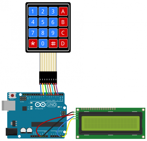
Keypad and LCD Connection Diagram
You can connect the keypad and LCD screen to Arduino using the connection diagram below.
Software:
#include <Wire.h>
#include <LiquidCrystal_I2C.h>
#include <Keypad.h>
const byte ROWS = 4;
const byte COLS = 4;
char hexaKeys[ROWS][COLS] = {
{'1', '2', '3', 'A'},
{'4', '5', '6', 'B'},
{'7', '8', '9', 'C'},
{'*', '0', '#', 'D'}
};
byte rowPins[ROWS] = {9, 8, 7, 6};
byte colPins[COLS] = {5, 4, 3, 2};
Keypad customKeypad = Keypad(makeKeymap(hexaKeys), rowPins, colPins, ROWS, COLS);
LiquidCrystal_I2C lcd(0x21, 16, 2);
void setup(){
lcd.backlight();
lcd.init();
}
void loop(){
char customKey = customKeypad.getKey();
if (customKey){
lcd.clear();
lcd.setCursor(0, 0);
lcd.print(customKey);
}
}
You need to add the I2C address of your LCD in line 20:
LiquidCrystal_I2C lcd (0x21, 16, 2);
My LCD's I2C address is 0x21, but yours will likely be different. The I2C address of your LCD should be provided in the datasheet, but if not, you can find it by running this I2C_Scanner.
Arduino Encrypted Lock Application
One of the most useful applications of a keypad is for keypad entry. You can set a password and have Arduino activate a relay or another module when the password is correct. The following code activates a 5V relay when the password is entered correctly:
#include <Wire.h>
#include <LiquidCrystal_I2C.h>
#include <Keypad.h>
#define Password_Length 8
int signalPin = 12;
char Data[Password_Length];
char Master[Password_Length] = "123A456";
byte data_count = 0, master_count = 0;
bool Pass_is_good;
char customKey;
const byte ROWS = 4;
const byte COLS = 4;
char hexaKeys[ROWS][COLS] = {
{'1', '2', '3', 'A'},
{'4', '5', '6', 'B'},
{'7', '8', '9', 'C'},
{'*', '0', '#', 'D'}
};
byte rowPins[ROWS] = {9, 8, 7, 6};
byte colPins[COLS] = {5, 4, 3, 2};
Keypad customKeypad = Keypad(makeKeymap(hexaKeys), rowPins, colPins, ROWS, COLS);
LiquidCrystal_I2C lcd(0x21, 16, 2);
void setup(){
lcd.init();
lcd.backlight();
pinMode(signalPin, OUTPUT);
}
void loop(){
lcd.setCursor(0,0);
lcd.print("Enter Password:");
customKey = customKeypad.getKey();
if (customKey){
Data[data_count] = customKey;
lcd.setCursor(data_count,1);
lcd.print(Data[data_count]);
data_count++;
}
if(data_count == Password_Length-1){
lcd.clear();
if(!strcmp(Data, Master)){
lcd.print("Correct");
digitalWrite(signalPin, HIGH);
delay(5000);
digitalWrite(signalPin, LOW);
}
else{
lcd.print("Incorrect");
delay(1000);
}
lcd.clear();
clearData();
}
}
void clearData(){
while(data_count !=0){
Data[data_count--] = 0;
}
return;
}
You can replace the "123A456" text with your own password in line 10:
char Master [Password_Length] = "123A456”;
The password length needs to be set in line 5:
#define Password_Length 8
The output pin that activates the relay is defined on line 6:
int signalPin = 12;
Once you've connected everything to Arduino, you'll have a circuit like this:

Share
Blog Latest Additions
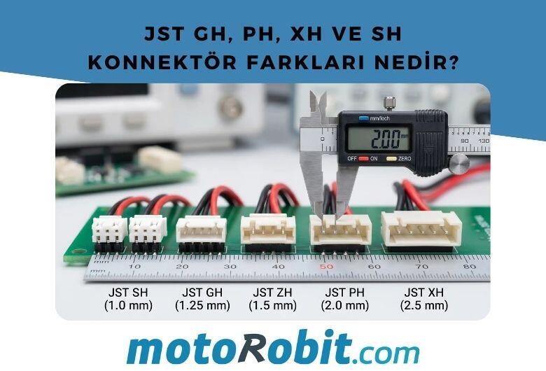
JST GH vs PH vs XH vs SH Connectors: Differences
27.06.2026

Low Level vs. What is High Level Trigger?
19.03.2026

The Code of Numbers on Drone Propellers: How to Read Propeller Measurements?
11.02.2026
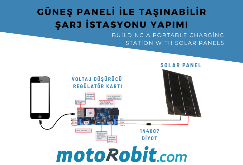
Building a Portable Charging Station with Solar Panels
10.01.2026

Differences Between Li-ion and Li-Po Batteries: Which Battery is Suitable for Which Project?
12.12.2025
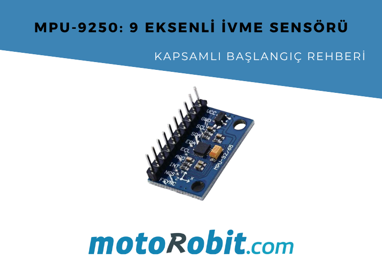
MPU-9250: 9-Axis Acceleration Sensor - A Comprehensive Beginner's Guide
28.10.2025