What is an Optocoupler IC?
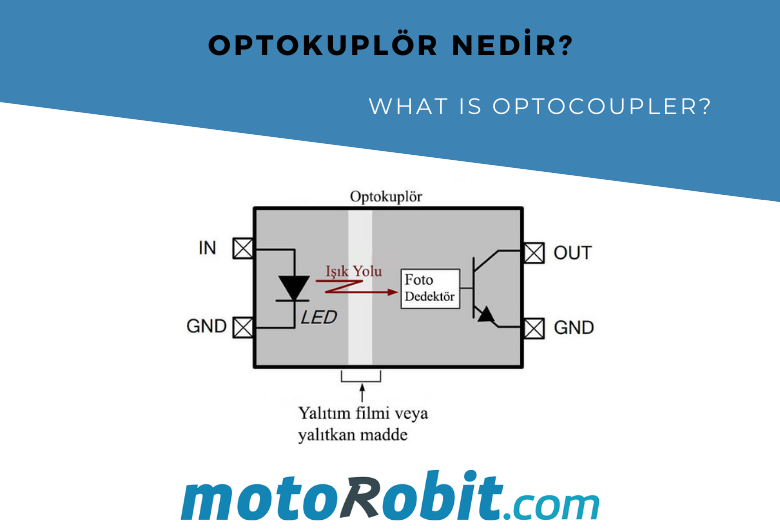
Optocoupler ICs, also known as optical isolators, are components that enable signal transmission between two circuits while maintaining electrical isolation. These components work by converting the signal from one circuit into light and then retransmitting it as an electrical signal in the other circuit. Here’s a detailed overview of what optocouplers are, how they work, and how to use them.
1. What is an Optocoupler?
An optocoupler, or optical isolator, is an integrated circuit that isolates input and output circuits optically while transmitting a signal via light. This feature is especially useful in high-voltage circuits or sensitive circuits that need protection—where an electrical connection between circuits of different potentials is undesirable. Optocouplers provide safe signal transmission by creating an optical connection.
2. Structure and Working Principle of an Optocoupler
An optocoupler typically consists of an LED and a photodetector (like a photodiode, phototransistor, or photo SCR). It operates as follows:
- When an electrical signal is applied to the LED on the input side, the LED emits light.
- This light, within an isolated environment inside the optocoupler, reaches the photodetector.
- The photodetector senses the light and converts it back into an electrical signal, generating an output signal.
Through this method, the electrical signal at the input is transmitted to the output while remaining isolated.
3. Applications of Optocouplers
Optocouplers are used in a wide range of electronic circuits. Here are some common applications:
- Industrial Control Systems: Used to provide isolation between control circuits and high-voltage machinery.
- Microcontroller Applications: Protects microcontrollers by isolating circuits operating at different voltage levels.
- DC-DC or AC-DC Converters: Ensures isolation between input and output circuits in power supply and converter circuits.
- Data Transmission Systems: Preferred in noisy environments to ensure secure signal transmission.
4. Types of Optocouplers
- Phototransistor Optocouplers: The most common type, used for low-speed signals.
- Photodiode Optocouplers: Preferred for high-speed data transmission applications.
- Photo SCR and Photo TRIAC Optocouplers: Ideal for controlling AC signals, especially in AC circuits.
- Photodarlington Optocouplers: Used when high gain is needed but has a slower response time.
5. How to Use an Optocoupler
Incorrect use of an optocoupler can render it ineffective or cause damage. Here’s a basic guide on setting up an optocoupler circuit:
Designing the Input Circuit: The LED side should be powered with an appropriate resistor. A series resistor limits the voltage and current applied to the LED. For instance, for a 5V input source and 20mA current, a 220Ω resistor would be suitable.
Designing the Output Circuit: The output photodetector should be connected to a load or a pull-up resistor. When the phototransistor is on, current flows, and an output signal is generated.
Checking Connections and Isolation: Ensure there is no direct connection between the input and output pins of the optocoupler. With this physical isolation, high voltages can be safely controlled.
6. Example Circuit Design
You can test optocoupler usage with an LED indicator or a simple microcontroller circuit. For example:
- Send a signal from a 5V microcontroller output to the LED side of the optocoupler.
- Connect the optocoupler's phototransistor output side to another circuit operating at 3.3V, providing isolated control between two different voltage sources.
Such circuits are especially useful for controlling sensors or relays in microcontroller projects safely.
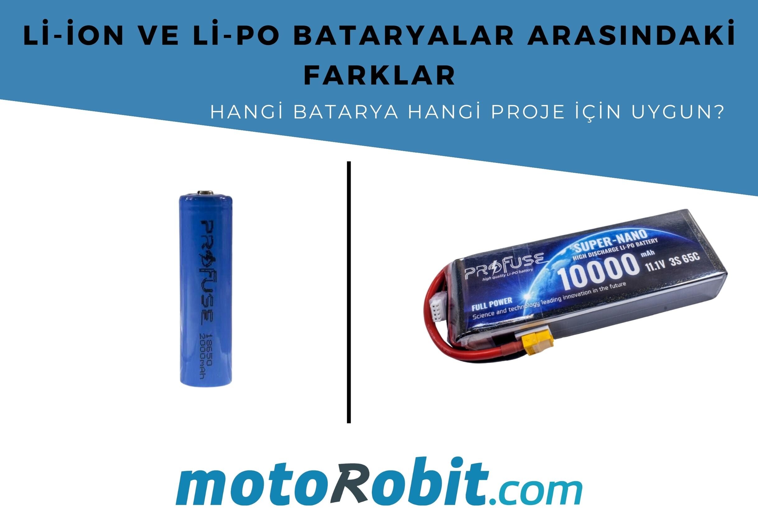
Differences Between Li-ion and Li-Po Batteries: Which Battery is Suitable for Which Project?
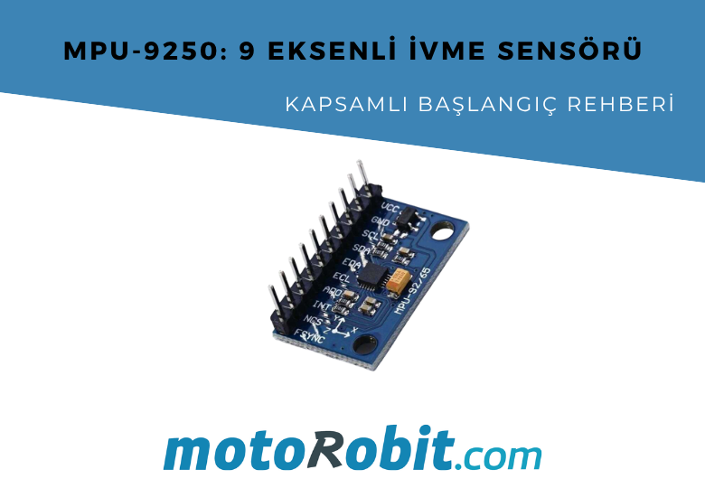
MPU-9250: 9-Axis Acceleration Sensor - A Comprehensive Beginner's Guide

What is ULN2003 ?
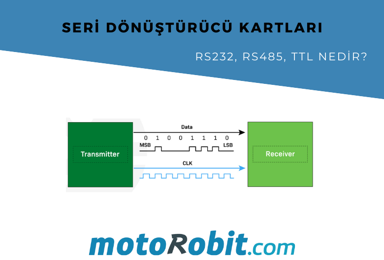
What are Serial Converter Cards (RS232, RS485, TTL)
What is Peltier and What is its Working Principle?

.png)