0
Comment
L298N DC Dual Motor Driver Circuit WB291111
154,00
TL
+
VAT
184,80
TL
Notify Me When It Arrives
Notify Me When It Arrives
L298N DC Dual Motor Driver Circuit WB291111
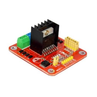
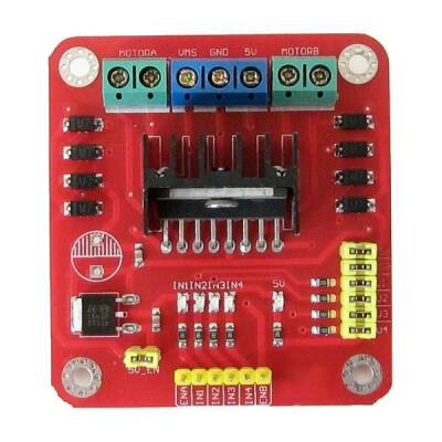
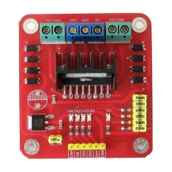
Wb291111 is a motor driver circuit with L298N motor driver IC. It can drive two dc motors or one 4-wire stepper motor.
Technical Specifications:
- Driver chip: L298N Dual H-bridge driver chip
- Supply voltage VMS: +5 V - 35 V-
- Maximum current: 2A / bridge
- VSS Logic supply voltage: 4 .5-5 0.5 V
- Input Control Signal Voltage Range: H: 4.5 ~ 5.5V / L: 0V
- Maximum Power Consumption: 20W
- Working Temperature: -25℃ to 130℃
- Driver Board Size: 55mm * 60mm * 30mm
- Driver Board Weight: 33g
- Other Functions: Direction Control Indicator LED, Power Indicator LED
Pin Connections:
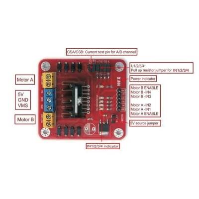
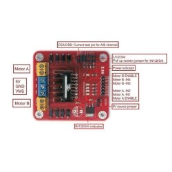
ENA: Pin that activates the left motor channel.
IN1 : Left engine 1st input
IN2: Left engine 2nd input
IN3: Right engine 1st input
IN4: Right engine 2nd input
ENB: Pin activating the right motor channel
MotorA: Left motor output
MotorB: Right motor output
VMS: Supply voltage input ( 4.8V-24V)
GND: Ground connection
5V: 5V output
There are additionally jumper-mounted pins on the product There is also space. These pins work optionally and are required to activate different features.
CSA: It is the current output of a motor driver channel. From here, the jumper can be removed and the current value can be read as analog voltage.
CSB: B is the current output of the motor driver channel. The jumper can be removed from here and the current value can be read as analog voltage.
V1: It is a jumper connected to the pull-up resistor that pulls the IN1 input directly to 5V. In this way, 5V will come to the ground unless you pull it continuously.
V2: It is a jumper connected to the pull-up resistor that pulls the IN2 input directly to 5V. In this way, 5V will come to the ground unless the pin pulls it continuously.
V3: It is a jumper connected to the pull-up resistor that pulls the IN3 input directly to 5V. In this way, 5V will come to the ground unless the pin pulls it continuously.
V4: It is a jumper connected to the pull-up resistor that pulls the IN4 input directly to 5V. In this way, 5V will come to the ground unless the pine draws continuously.
5V-EN: Jumper that makes the 7805 line active and passive. The 5V output becomes active and 5V can be drawn from here. If you take it off, this hat will become inactive.
SIMILAR PRODUCTS
.png)
