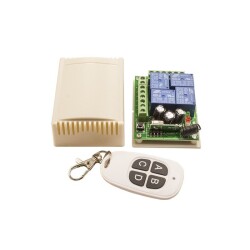
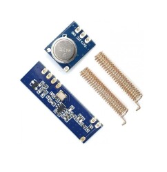
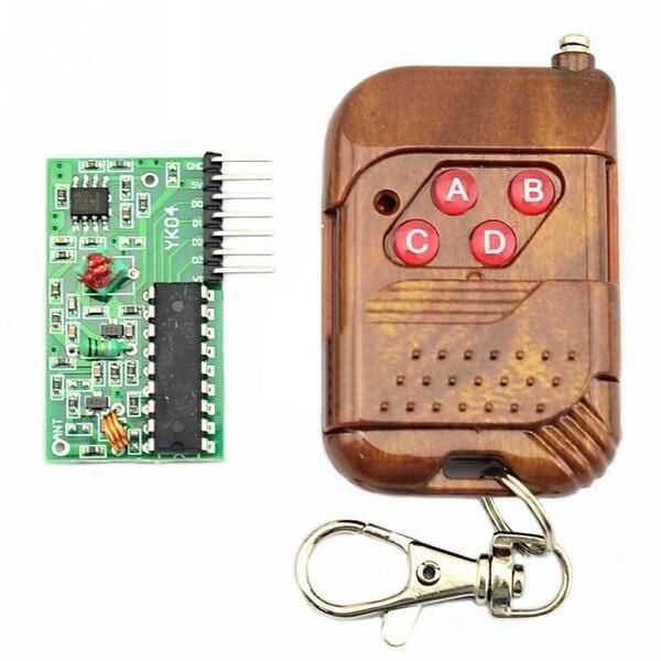
4 Channel receiver, 4 button transmitter control set. A fixed code quad radio receiver circuit can be easily constructed by remote control of four four-bit data output codes corresponding to the module.
There are four buttons on the remote control and the receiver card respectively corresponds to the four data bits on output pin D0, D1, D2 and D3. Press the buttons to transmit signals, the output of the corresponding data bit is high.
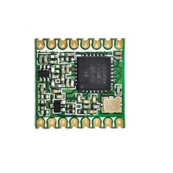
Caution: When handling the receiver module, be careful not to touch the copper coil (inductor) on it. Applying some physical movement to the coil changes the inductance value, which can cause improper circuit operation.
How it works:
1. When a key is pressed, the IC connects to the power supply battery and starts transmitting packets at a frequency of 315 Mhz consisting of the ID and Data byte indicating which key was pressed. This information is used in remote control applications.
2. Each transmitter has a unique pre-programmed ID set during manufacturing and cannot be changed. The receiver card usually keeps the identity of the transmitter in its memory beforehand, so that the receiver responds only to the identity of the known transmitter for secure applications.
3. The RF part inside the remote is a SAW based 315 Mhz transmitter which can be received by any 315 Mhz type ASK RF Receiver followed by the decoder chip.
Note: By default, this remote control module comes with Anti-Lock mode.
Specifications
Transmitter Remote control:
- Modulation mode: ASK (Amplitude Modulation).
- Encoder types: fixed code.
- Decoding receiver card:
- Receiver Operating voltage: DC 5V.
- Receiver sensitivity: -98dB.
- Pin 7 bits: VT, D3, D2, D1, D0, +5V and GND.
- VT is a valid signal high output pin when a valid signal is received , high pin output can also operate the relay.
- Dimension: 7 x 22 x 41 mm.
Pin Connection and Functions:
- 1.VT output status indicator.
- 2.D3 data output.
- 3.D2 data output.
- 4.D1 data output.
- 5.D0 data output.
- 6.5V power supply positive.
- 7.GND power supply negative.
- 8.ANT connects the antenna terminal .
A total of eight external receiver module interfaces. “5V” means positive power supply, “D0, D1, D2, D3” represents output, “GND” means power supply is negative, “ANT” means connect antenna terminal.
Pro- distance requirements, then the best quarter wavelength antenna, usually use a 50-ohm single wire, the length of the antenna is about 17 cm.


.png)