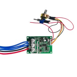
Apart from DC motors, it also allows stepper motor control.
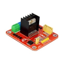
Pin Links :
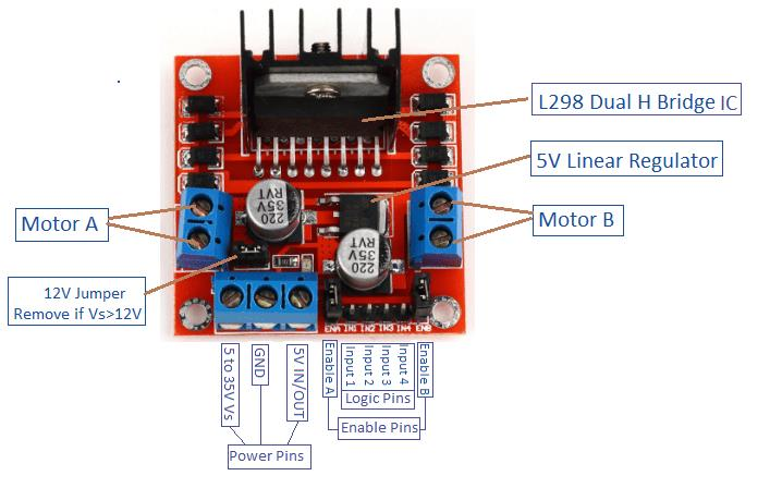
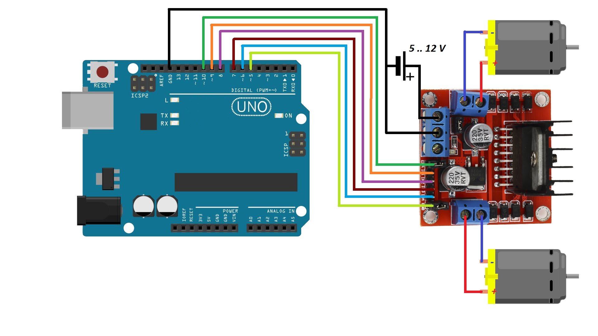
ENA: Left motor channel activation pin
IN1: Left motor 1st input
IN2: Left engine 2nd trip
IN3: Right engine 1st. inlet
IN4: Right engine 2nd inlet
ENB: Right motor channel activation pin
MotorA: Left motor output
MotorB: Right motor output
VCC: Supply voltage input(4.8V-24V)
GND: Ground connection
5V: 5V output
There are also pins with jumpers on the product. These pins can be used for optional uses and to activate different features.
CSA: A is the current output of the motor driver channel. By removing the jumper from here, the current drawn can be read as analog voltage.
CSB: B is the current output of the motor driver channel. By removing the jumper from here, the current value drawn can be read as analog voltage.
V1: It is connected to the pull-up resistor that directly pulls the IN1 input to 5V. It is a jumper. In this way, 5V will always come to the pin unless you pull it to ground.
V2: It is connected to the pull-up resistor that directly pulls the IN2 input to 5V. It is a jumper. In this way, 5V will always come to the pin unless you pull it to ground.
V3: It is connected to the pull-up resistor that directly pulls the IN3 input to 5V. It is a jumper. In this way, 5V will always come to the pin unless you pull it to ground.
V4: It is connected to the pull-up resistor that directly pulls the IN4 input to 5V. It is a jumper. In this way, 5V will always come to the pin unless you pull it to ground.
5V-EN: It is the jumper that makes the 7805 line active and passive. When plugged in, the 5V output of the card becomes active and 5V can be drawn from there. If it is removed, this line becomes passive.


.png)