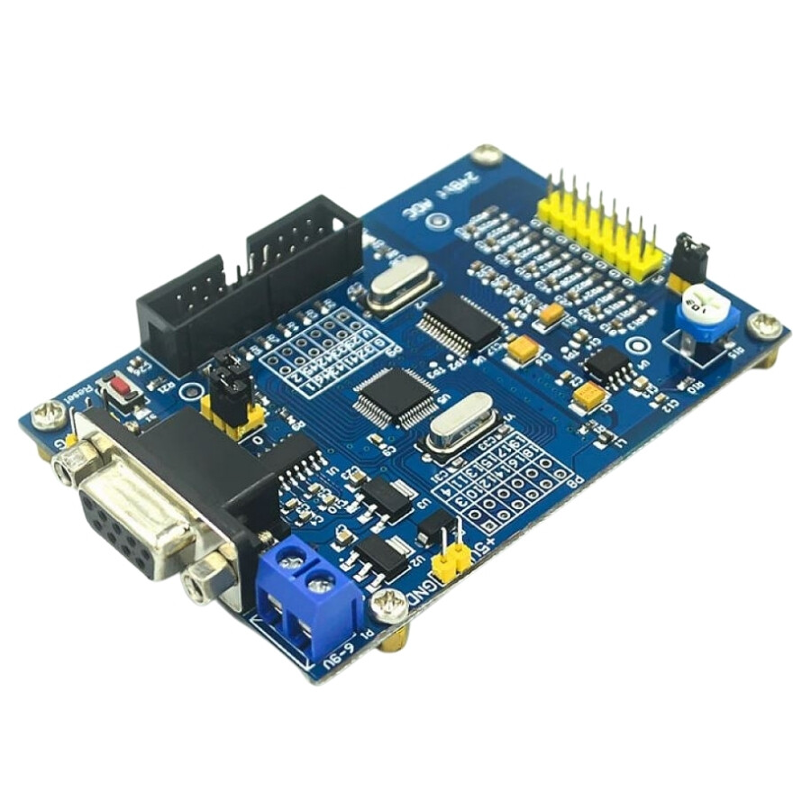
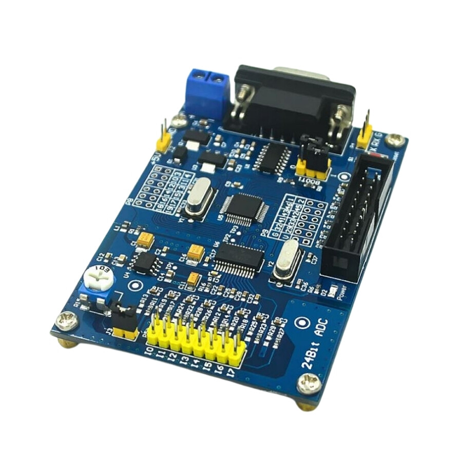
ADS1256 24-bit AD High Precision ADC STM32F103C8T6 Module
It has taken all the IO ports of the STM32F103C8T6 microcontroller and users can develop their own functions. The program can be downloaded via serial port. The reference voltage of the AD chip is 2.5V.
A potentiometer is provided on the board to test the AD input. The voltage generated by the voltage divider of the potentiometer is connected to AN0 through jumper S3, which is convenient for debugging the board without a sensor. If you do not use this test, you can remove the S3 jumper and enter the test voltage directly from AN0-AN7. (Voltage input to AD input cannot be higher than 5V).
Technical Specifications
- Input voltage range: 5.5-12 volts
- Power supply input terminal: 5V
- Power supply voltage: The power supply has anti-reverse function and built-in 5V and 3.3V regulator components. It is also compatible with 9V external DC power supplies.
- 8 MHZ for the crystal, 9 MHZ for the chip's internal frequency and 72 MHZ for the operating frequency
- Ultra-high precision, low temperature drift
- Size: 87mm x 59mm
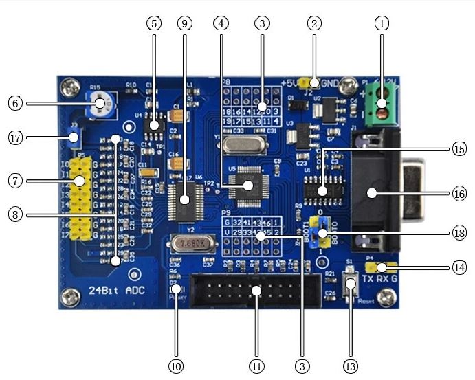
- Power input terminal, input voltage range 5.5V - 12V (5V power supply, please connect directly to 2)
- 5V power supply input terminal (1.2 two power supply, only one can be connected)
- STM32F103C8T6 leads GPIO, suitable for secondary development.
- MCU: STM32F103C8T6
- 2.5V benchmark, ultra-high sensitivity, low temperature deviation
- Adjustable potentiometer, output adjustable voltage is connected to AIN0/I0
- Collect 8 input channels, I0-I7 is connected to the positive terminal of the collection voltage, G is analog ground, and the negative terminal of the collection voltage is connected
- Input filter and attenuation resistor are not attenuated by default, leaving the position of solder attenuation resistor, 0603 package
- ADS1256IDB acquisition chip
- Power indicator LED
- JTAG interface designed according to JLINK-V8 or V9 definition
- Unmarked
- STM32F103C8T6 reset button
- Corresponding to TX, RX, GND of MCU Incoming USB to TTL wiring, can directly communicate with the computer
- 3232 serial communication chip
- Serial port header
- Adjustable potentiometer to I0/AIN0 on/off control output voltage: Disconnect floating IO, connect I0 to measure adjustable potentiometer output voltage terminal
- STM32 selects BOOT0 and BOOT1 control jumper headers


.png)