.png)

0
Comment
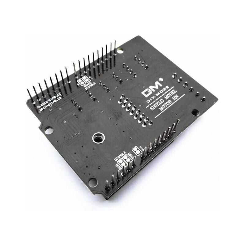
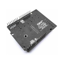
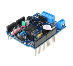
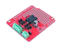
L298NH 2A Arduino Dual Motor Driver Shield
488,25
TL
+
VAT
585,90
TL
Notify Me When It Arrives
Notify Me When It Arrives
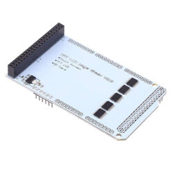
L298NH 2A Arduino Dual Motor Driver Shield
The L298NH Motor Shield is based on the L298N, a dual full bridge driver designed to drive inductive loads such as relays, solenoids, DC and stepper motors. It allows you to drive two DC motors with your Arduino board, controlling the speed and direction of each independently. You can measure the motor current absorption of each motor, among other features.
Technical Specifications
- Operating Voltage 5V - 12V
- Motor controller L298HN, 2 DC motors or 1 stepper motor Drive
- Maximum current per channel 2A or maximum 4A (with external power supply)
- Current detection 1.65V/ A
- Free-running stop and brake function
Supply Voltage
The Motor Shield can only be connected to an external power supply It must be powered by . Because the L298HN integrated into the product has two separate power connections, one for the logic and one for the motor supply driver, the Required motor current often exceeds the maximum USB current rating.
External (non-USB) power is an AC-DC It may come from the adapter or the battery.
In order to avoid any possible damage to the Arduino board on which the Shield is mounted, we recommend that you use an external power supply that provides voltage between 7 and 12V. The shield can provide 2 amps per channel, for a maximum of 4 amps.
L298NH Input and Output Pins
L298NH, A and B designation It has two separate channels supplied, each using 4 of the Arduino pins to drive or sense the motor. There are a total of 8 pins in use on this shield. You can use each channel individually to drive two DC motors, or combine them to drive a bipolar stepper motor. The shield's pins separated by channel are shown in the table below:
Function pins per ch. One pin per ch. B
Direction D12 D13
PWM D3 D11
Brake D9 D8
Current Detection A0 A1
To Brake and If you do not need Current Sensing and also need more pins for your application, you can disable these features by cutting the relevant jumpers on the back of the shield.
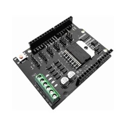
Motor Connection
Brushed DC motor. You can drive two Brushed DC motors by connecting two wires each to the (+) and (-) screw terminals for each channel A and B. You can control the speed by changing the PWM A and PWM B duty cycle values with DIR B pins. The Brake A and Brake B pins, if set to HIGH, effectively brake the DC motors rather than allowing them to slow down by removing power. You can measure the current passing through the DC motor by reading the SNS0 and SNS1 pins. Each channel will have a voltage proportional to the measured current, which can be read as a normal analog input via the analogRead() function on analog input A0 and A1. For your convenience, the channel is calibrated to be 3.3V when delivering the maximum possible current, i.e. 2A.
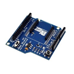
SIMILAR PRODUCTS
325,50
TL
+
VAT
488,25
TL
+
VAT
209,25
TL
+
VAT
120,90
TL
+
VAT
232,50
TL
+
VAT
604,50
TL
+
VAT
279,00
TL
+
VAT
104,63
TL
+
VAT
81,38
TL
+
VAT
465,00
TL
+
VAT
441,75
TL
+
VAT